 |
|||
|
|
|||
|
Page Title:
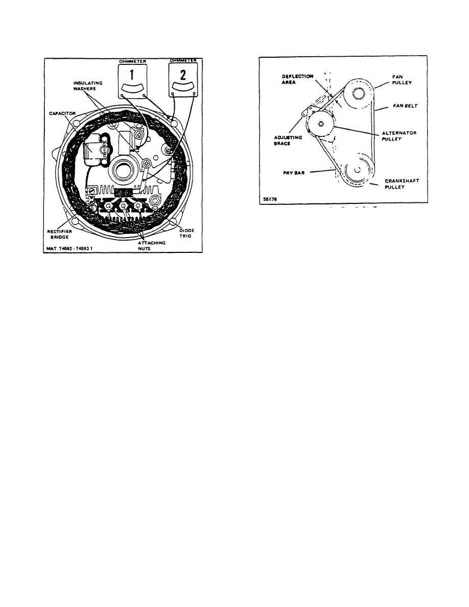
Figure 2-6. End Frame Assembly, Inside View |
|
||
| ||||||||||
|
|
 TM 10-3930-644-14 & P
Figure 2-7. Fan Belt Tension
1. Disconnect the battery from the electrical circuit
prior to alternator removal/installation.
2. Disconnect and properly label the "BAT"
Figure 2-6. End Frame Assembly, Inside View
(Battery), No. I and No. 2 terminal leads at the
alternator.
D. ADJUSTMENT
3. Loosen the adjusting brace and the pivot
Be sure to check the mounting bolts for tightness and
mounting bolt, then push alternator towards
the belt for alignment, correct tension and wear. Belt
engine until fan belt is disengaged from the
tension should be adjusted to allow approximately .375"
alternator pulley.
inward deflection of the belt between the alternator
pulley and the fan pulley with a force of about 10
4. Carefully remove the alternator from the engine
pounds. (See Figure 2-7)
as the pivot mounting bolt and adjusting brace
capscrew are removed.
When tightening belt tension always apply pressure
against the stator laminations, never against the end
F. SERVICE
frames. Inspect the brush springs and brushes for
evidence of any damage, wear or corrosion. Replace
Proceed according to the following sequence.
any brush springs or brushes in doubtful condition.
1. Disassembly
A noisy alternator can be caused by worn or dirty
bearings, loose mounting bolts, a loose drive pulley, a
To disassemble the alternator, take out the four
defective diode or a defective stator.
thru-bolts, and separate the drive end frame and
rotor assembly from the stator assembly by
E. REMOVAL
prying apart with a screwdriver at the stator slot.
A scribe mark will help locate the parts in the
Alternator: After extensive periods of operation or during
same position during assembly.
major engine overhaul, the alternator should be removed
from the truck for a thorough inspection and cleaning of
After disassembly, place a piece of tape over the
all parts.
The alternator consists of four main
slip ring end frame bearing to prevent entry of
components which includes the two end frames, the
dirt and other foreign material, and also place a
stator and the rotor. The following procedures should be
piece of tape over the shaft on the slip ring end.
used for proper removal:
If brushes are to be reused, clean with a soft dry
cloth.
R-146-1
3-85
|
|
Privacy Statement - Press Release - Copyright Information. - Contact Us |