 |
|||
|
|
|||
|
|
|||
| ||||||||||
|
|
 TM 10-3930-644-14 & P
C. TROUBLESHOOTING PROCEDURES
1. Undercharged Battery
Close adherence to the following procedures in the order
This condition, as evidenced by slow cranking
presented will lead to the locations of charging system
and low specific gravity readings, can be caused
defects in the shortest possible time. Only a portion of
by one or more of the following conditions, even
those procedures need be performed. It will never be
though the ammeter may be operating normally.
necessary to perform all the procedures in order to
locate the trouble.
a. Insure that the undercharged condition
has' not been caused by accessories
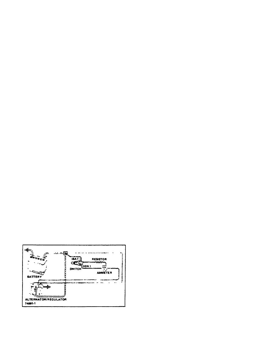
A basic wiring diagram showing lead connections is
having been left on for extended periods.
shown in Figure 2-4. To avoid damage to the electrical
equipment, always observe the following precautions:
b. Check the drive belt for proper tension.
1. Do not polarize the alternator.
c. If a battery defect is suspected, check the
battery as described in the Battery Service
2. Do not short across or ground any of the
section.
terminals in the charging circuit except as
specifically instructed herein.
d. Inspect the wiring for defects. Check all
connections for tightness and cleanliness,
3. NEVER operate the alternator with the output
including the slip connectors at the
terminal open-circuited.
alternator and firewall, and the cable
clamps and battery posts.
4. Make sure the alternator and battery have the
same ground polarity.
e. With ignition on and all wiring harness
leads connected, connect a voltmeter
5. When connecting a charger or a booster battery
from:
to the vehicle battery, connect negative to
negative and positive to positive.
alternator "BAT" terminal to ground,
Trouble in the charging system will shot up as one or
alternator No. 1 terminal to ground, and
more of the following conditions:
alternator No. 2 terminal to ground.
1. Faulty ammeter operation.
A zero reading indicates an open between
2. An undercharged battery as evidenced by slow
voltmeter connection and battery. The
cranking and low specific gravity readings.
alternator has , built-in feature which
avoids overcharge and accessory damage
3. An overcharged battery
as
evidenced
by
by preventing the alternator from turning
excessive water usage.
on if there is an open in the wiring harness
connected to the No. 2 terminal. Opens in
the wiring harness connected between-the
No. 2 terminal and battery may be
between the terminals, at the crimp
between the harness wire and terminal, or
in the wire.
f. If previous Steps a. through e. check
satisfactorily, check the alternator as
follows:
(1) Disconnect battery ground cable.
(2) Connect an ammeter in the circuit at
the "BAT" terminal of
Figure 2-4. Alternator Typical Wiring Diagram
R-146-1
3-83
|
|
Privacy Statement - Press Release - Copyright Information. - Contact Us |