 |
|||
|
|
|||
|
|
|||
| ||||||||||
|
|
 TM 10-3930-644-14 & P
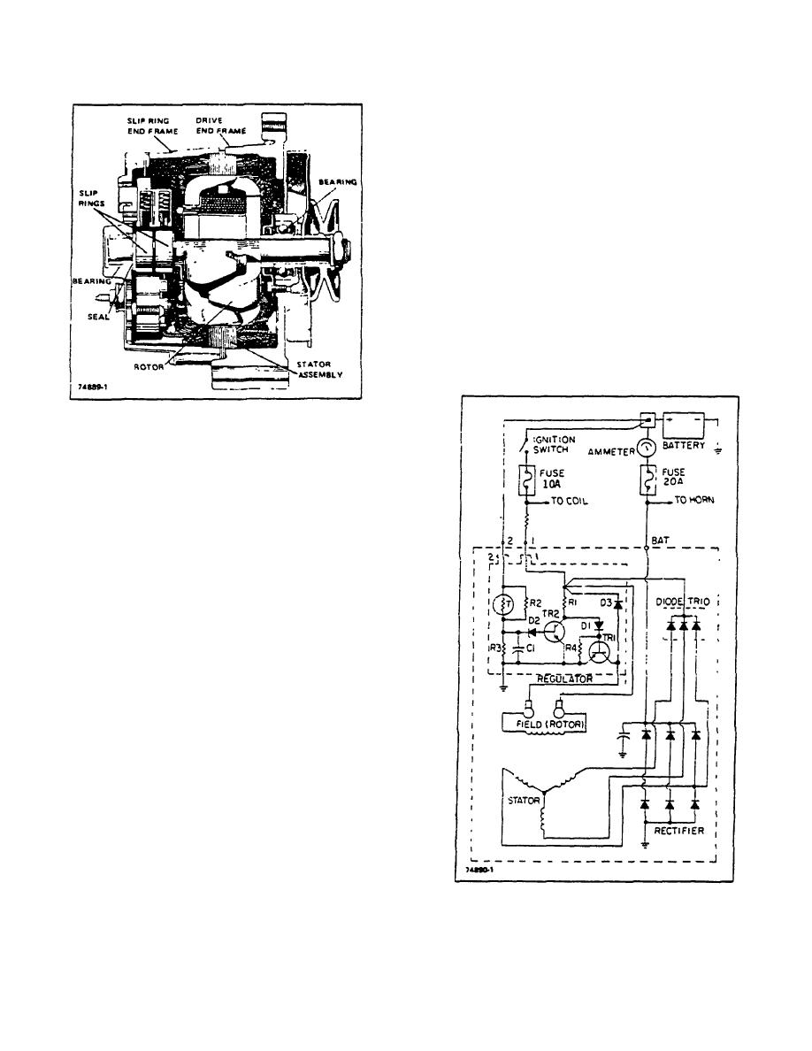
current is limited to a negligible value by the high
resistance of R2 and R3. As the alternator speed and
voltage Increase, the voltage between R2 and R3
increases to the point where zener diode 02 conducts.
Transistor TR2 then turns on and TRI turns off. With TRI
off, the field current and system voltage decrease, and
D2 then blocks current flow, causing TRI to turn back on.
The field current and system voltage increases, and this
cycle then repeats many times per second to limit the
alternator voltage to a preset value.
Capacitor C1 smoothes out the voltage across R3,
resistor R4 prevents excessive current through TRI at
high temperatures, and diode D3 prevents high-induced-
voltages in the field windings when TR1 turns off,
Resistor R2 is a thermistor which causes the regulated
voltage to vary with temperature, thus providing the
optimum voltage-for charging the battery.
Figure 2-2. Cross-Sectional View of Alternator
B. PRINCIPLES OF OPERATION
The principles of operation of the alternator are as
follows. See Figure 2-3.
When the Ignition switch is closed, current from the
battery flows through the 10-ampere fuse and resistor to
the alternator No. 1 terminal, through resistor R1, diode
DI, and the base-emitter to transistor TRI to ground. and
then back to the battery. This turns on transistor TR1,
and current flows through the alternator field coil and
TR1 back to the battery. The ammeter shows discharge.
The resistor in parallel with the ammeter reduces total
circuit resistance to provide higher field current for initial
voltage build-up when the engine starts.
With the alternator operating. a.c. voltages are
generated in the stator windings, and the stator supplies
d.c. field current through the diode trio, the field, TR1,
and then through the grounded diodes in the rectifier
bridge back to the stator. Also, the six diodes in the
rectifier bridge change the stator a.c. voltages to a d.c.
voltage which appears between ground and the
alternator "SAT" terminal.
As alternator speed
increases, current is provided for charging the battery
and operating electrical accessories. Also, with the
alternator operating, the same voltage appears at the
"BAT" and No. 1 terminals, and the ammeter shows
charge to Indicate the alternator is producing voltage.
Figure 2-3. Alternator Internal Circuits, Schematic
The No. 2 terminal on the alternator is always connected
Diagram
to the battery, but the discharge
R-146-1
3-82
|
|
Privacy Statement - Press Release - Copyright Information. - Contact Us |
