 |
|||
|
|
|||
|
|
|||
| ||||||||||
|
|
 TM 10-3930-644-14 & P
TOPIC 5. ACCELERATOR LINKAGE
A. DESCRIPTION
5. Turn accelerator pedal stop screw in or OUT
The accelerator linkage provides manual, foot pedal
and tighten locknut to adjust pedal to desired
control of the engine speed by either increasing or
pedal release height.
decreasing the fuel flow to the carburetor. Maximum
speed (RPM) is controlled by the governor assembly,
C. PEDAL AND LINKAGE REMOVAL
which is preadjusted at the factory.
1. Pedal. Remove "E" clip from pedal hinge pin,
B. MAINTENANCE AND ADJUSTMENT
slide pin out of pedal and bracket and remove
pedal (Figure 5-1 and 5-2).
Inspect linkage for security of mounting presence of
pins, spring tension and proper action.
2. Shaft Roller, Remove nut and lockwasher from
bearing capscrew, and remove capscrew,
Periodically lubricate moving parts of linkage, except
bearing and two plain washers.
shaft mounting blocks.
3. Accelerator Shaft.
Remove capscrews and
Adjust of linkage may become necessary because of
lockwashers which attach shaft mounting blocks
improper spring action, bent parts or replacement parts.
to front panel or bracket and-'remove assembly
from truck. To remove mounting blocks, remove
1. Ensure that all mechanical' connections are
roll pin from accelerator lever and shaft. Slide
securely made, as indicated in accelerator and
lever and mounting blocks off shaft. Remove
linkage exploded view, Figures 5-1 and 5-2.
spring.
2. Inspect carburetor throttle lever position; throttle
should be in fully CLOSED position with
accelerator pedal released.
3. Have assistant push fully downward on the
accelerator pedal; accelerator rod or cable will
pull adjustable yoke, attached to throttle lever,
(overcoming pressure of CLOSED throttle return
spring), and carburetor throttle will OPEN fully.
4. Release pedal. Throttle should now be fully
CLOSED.
Adjust accelerator rod or cable
throttle yoke in or OUT to ensure a fully
CLOSED condition (with accelerator pedal
released).
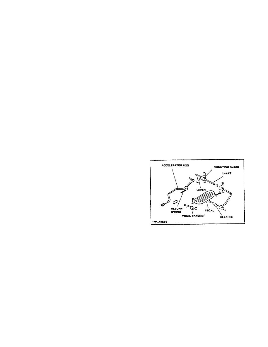
Figure 5-1. Accelerator and Linkage (Type I)
R-123-1
3-67
|
|
Privacy Statement - Press Release - Copyright Information. - Contact Us |
