 |
|||
|
|
|||
|
|
|||
| ||||||||||
|
|
 TM 10-3930-644-14&P
c. Insert throttle shaft and lever assembly in
NOTE
throttle body. Rotate shaft to wide open;
Do not bend, twist or apply pressure
then insert throttle plate in shaft and rotate
on the float bodies. The float bodies
to close position, holding plate in position
when viewed from the free end of the
with fingers. Make certain beveled sides
bodies must be centered and at right
of plate fit against throttle bore when plate
angles to the machined surface and
is closed.
must move freely on the float axle.
d. Start throttle plate screws, leaving screws
loose. Close throttle plate several times,
making sure plate is centered in throttle
bore. Then tighten screws, using small
screwdriver.
e. Install idle adjusting needle and friction
spring in threaded passage at side of
throttle body.
Turn needle in lightly
against its seat, then back out needle 1-
1/4 turns as a preliminary adjustment.
f. Install idle jet in machined surface of
throttle body.
g. Install fuel valve seat and fiber washer.
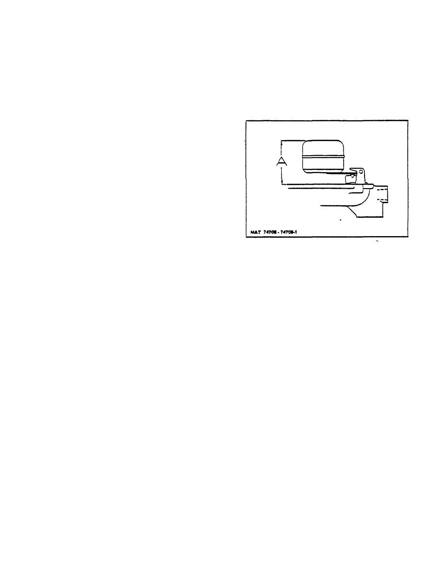
Figure 8. Float Setting
h. Install venturi in throttle bore, large
4. Assembly of Throttle and Fuel Bowl Bodies
opening end first. Then place new bowl to
body gasket on machined surface of
a. Place fuel bowl assembly in position on
throttle body, making sure venturi flange is
throttle body, being careful not to damage
set in throttle body recess below gasket.
floats. Then align holes in fuel bowl with
holes in gasket and throttle body.
i. Install fuel valve needle in seat and
position float assembly in hinge bracket.
b. Install four bowl to body screw and
lockwasher assemblies and tighten throttle
J. Insert float axle through hinge bracket and
body.
float lever bushing from side opposite slot
in hinge bracket with fingers only. Then
c. Install hex head plug and filter screen (if
press float axle through slotted side of
used) in threaded passage in throttle
bracket, using handle of screwdriver.
body.
k. To insure correct fuel level in the float
d. With throttle held in closed position, turn
chamber, check distance "A" from top of
throttle stop screw in until stop screw just
floats to machined surface of throttle body
contacts throttle stop and then turn stop
(no gasket) with throttle body inverted, see
screw in 1-1/2 additional turns as a
Figure 8. This dimension should be 1-
preliminary idle speed setting.
5/32" plus or minus 1/32". To increase or
decrease distance from top of float bodies
to machined surface, use long nose pliers
and bend lever close to float body.
3-66e
|
|
Privacy Statement - Press Release - Copyright Information. - Contact Us |
