 |
|||
|
|
|||
|
Page Title:
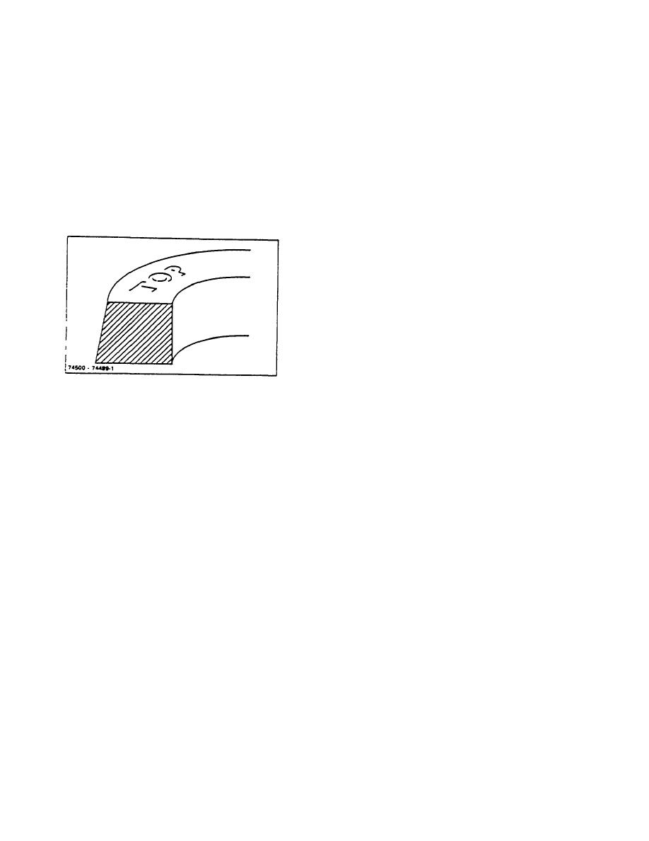
Figure 8-11. Install Tapered Rings with "Too" Side Up |
|
||
| ||||||||||
|
|
 TM 10-3930-644-14&P
5. Pin milled application install gap of expander
Secure connecting rod to crankshaft, replace rod bearing
cap and capscrews and torque to 40-45 lb. ft.
spacer 90 from pin, with hump of expander over
pin and ends butted. Install top segment, then
When pistons are ready for installation in the cylinders,
bottom segment with gaps of segments over pin.
compress rings carefully using a good ring compressor.
A light tap on the head of the piston will allow the
To install the balance of the rings, use a ring tool with
assembly to go into the cylinder very easily. If any
recess side up and place the ring in with the bottom side
difficulty in tapping piston and ring assembly into the
up. Start with the lowest ring first.
cylinder is encountered, the compressor should be
removed and rings checked for correct installation in the
Some piston rings are taper faced. These are clearly
groove.
marked "TOP" on the side to be up when assembled on
piston (Figure 8-11).
Measure the running clearance between piston and
cylinder bore as described in preceding paragraph E.
Piston and Piston Ring Inspection. The clearance is
critical and should be accurate. Pistons are available for
redimensioned cylinder bores in .020", .030", .040" and
.060" oversizes.
Hold the feeler stock along the side of the cylinder bore
at bottom of crankcase. With rod connected insert the
piston into the cylinder bore in running position. With the
correct clearance between the piston and cylinder bore,
the .003" feeler gauge can be with drawn with a slight
pull. The pull should not exceed 5 to 10 pounds. Test
the clearance at the end of the piston pin and at points
90 from the ends of the pin.
Figure 8-11. Install Tapered Rings with "Too" Side Up
When fitting a piston to a new or accurately resized bore,
Position ring in the tool so the expanding fingers will fully
the bore inner diameter should be the same at top and
engage both ends.
bottom. Therefore, the clearance may be taken at either
end. In bores that have been worn, but not resized,
Apply pressure on handles so ring is completely
some taper giving extra clearance at the top of the bore
expanded. Pass the expanded ring and tool recessed
is likely. In such cases, the clearance must be checked
side down over the piston to the proper groove.
at the bottom of the bore where the wear is least and the
fit is closest.
CAUTION
NOTE
If piston is equipped with a steel
Although the connecting rod bearing
groove insert, this insert must be
side clearance is less critical than the
installed on top of the number one
bearing running clearances, no
ring. (The steel groove insert is not
bearing should be assembled without
part of the re-ring kit, and can be re-
checking the side clearance.
used when replacing rings.)
Check the side play of the rods by forcing the connecting
I. INSTALLATION
rod fully to one side or the other. Insert a feeler gauge
between the crankshaft and bearing edge. The desired
Oil all rings and pistons before installing them in the
side play is from .0100" to .0060". If the clearance is
cylinder bore.
excessive, the rod must be replaced. If there is no side
Replace pistons in the same manner as they are
play, the piston and connecting rod must be removed
removed, through the top of the cylinder bore. Care
and checked to determine cause of binding.
should be taken to keep the piston rings properly seated
and staggered during insertion.
Reinstall oil pan gasket and oil pan. (Refer to TOPIC 15.
OIL PAN,)
NOTE
Ensure that pistons, connecting rods
Reinstall engine.
(Refer to TOPIC 17.
ENGINE
and rod caps are all replaced in their
REMOVAL/INSTALLATION.)
respective cylinder locations as
removed.
R-104-1
3-32
|
|
Privacy Statement - Press Release - Copyright Information. - Contact Us |
