 |
|||
|
|
|||
|
Page Title:
TOPIC 9. CAMSHAFT, CAMSHAFT BEARINGS, AND VALVE TAPPETS |
|
||
| ||||||||||
|
|
 TM 10-3930-644-14&P
TOPIC 9. CAMSHAFT, CAMSHAFT BEARINGS, AND VALVE TAPPETS
A. REMOVAL
9. If wear is found to be in the bushings instead,
these must be replaced using precision service
bushings, available for that purpose, which
1. Refer to TOPIC 17 for engine removal. Refer to
require no reaming, only care In assembly, to
TOPIC 18 or 19 for governor removal and
line up oil holes, and not damage the bushings
camshaft access. Remove camshaft gear nut.
as they are being pressed in.
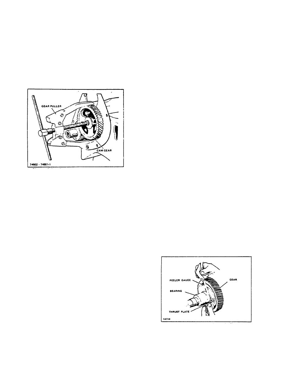
2. Using a Duller, remove the cam and crank gears
(Figure 9-1).
CAUTION
When installing camshaft use special
care to prevent camshaft bumping,
and loosening expansion plug which
cause an oil leak.
B. INSPECTION
1. Checking Camshaft End Play Camshaft end
play is controlled by the thrust plate. The actual
distance which the shaft may move forward or
rearward depends upon the distance between
the rear face of the gear and the front face of the
cam journal, minus the thickness of the thrust
plate. Thus, when a condition of excessive
camshaft end clearance s; found, it may be
corrected by reducing the distance between the
journal and the gear, or by installing a new thrust
Figure 9-1. Removing Cam Gear with Puller (Typical)
plate to replace the one which has been worn
too thin. If both the thrust plate and the thrust
3. Remove the screws holding the camshaft thrust
surfaces of the gear and journal are worn, it will
plate to the front of the cylinder block, which
be necessary to machine a small amount from
makes it possible to pull the camshaft forward
the shoulder against which the rear face of the
out of the bearings.
gear hub seats.
4. Unless engine is lying on its side, tappets must
be removed or lifted before camshaft can be
Remove enough so that a .005" to .009" feeler
pulled.
gauge may be fitted between the front of the
5. Remove tappet chamber cover.
journal and the rear of the thrust plate when the
6. Tappets can then be lifted out and lined up in
gear is assembled (Figure 9-2). If a condition of
sequence, for installation in the same location
insufficient end play is found, use one or two thin
unless inspection shows that they require
shims between the shoulder and the gear.
replacement. Refer to TOPIC 4. VALVES
INTAKE AND EXHAUST.
7. Before pulling the camshaft completely, check
the clearance of the bearing journals in the
bushing (or block in some models). To do this
use strips of feeler stock .25" wide with edges
dressed with a stone to eliminate any burrs or
feathered edges.
8. If clearance is equal to or greater than the wear
limits specified in TOPIC 1.
FITS AND
TOLERANCES, check the diameter of the
camshaft-journals to determine the next step.
Excess wear at these positions require
replacement of the shaft.
Figure 9-2. Checking Camshaft Thrust Clearance
R-104-1
3-33
|
|
Privacy Statement - Press Release - Copyright Information. - Contact Us |
