 |
|||
|
|
|||
|
Page Title:
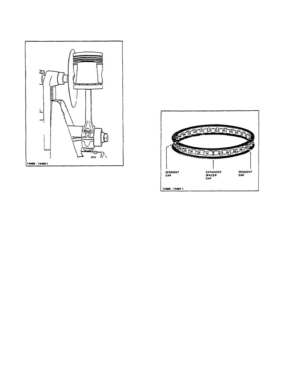
Figure 8-9. Checking Connecting Rod Assembly for Alignment |
|
||
| ||||||||||
|
|
 TM 10-3930-644-14&P
After rings have been properly fitted, install them on
piston, using a piston ring remover and installer. Take
care not to spread rings more than necessary. Stagger
ring gaps evenly around piston so that no two are in line.
Grip the connecting rod in a vise with lead lined jaws to
hold the piston firmly and roll each of the straight side
rings in its groove to be sure there are no burrs or other
interference with the free action of the ring in the groove.
The 3-piece oil ring (Figure 8-10) should be installed first
on the piston, from the top side so that the piston skirt
will not be scratched.
Figure 8-9. Checking Connecting Rod Assembly for
Alignment.
H. FITTING PISTON RINGS
Figure 8-10. Three-Piece Oil Ring
Check gap between ends of piston rings before rings are
installed on piston. Select rings to be installed on each
Install oil control ring as follows:
piston and insert them one at a time into cylinder bore in
which they are to operate. Use a piston to push ring
1. Place stainless steel expander spacer of three
squarely into cylinder bore so that it is parallel with top of
piece ring in oil groove with ends butted.
cylinder block (Figure 8-2).
2. Install steel segment on top of e pander spacer
x
Check the ring side clearance with a feeler gauge
with gap of segment approximately 90 beyond
(Figure 8-3) at various positions, in accordance with the
gap of stainless steel expander, making certain
tolerances
shown
in
TOPIC
1,
FITS
AND
expander remains butted.
TOLERANCES.
3. Install second segment on bottom side of
expander
spacer
with
segment
gap
Measure ring to groove clearance (top of ring to top of
approximately 90 from expander spacer gap in
groove in piston). The clearances for the two engines
opposite direction from which top segment has
are specified in the following table. Use a feeler gauge
been positioned.
of the proper dimension to check the clearance.
4. Recheck installation oil control ring should be
free to move in the groove: however, a slight
Piston Ring
Clearance
drag will be noticed due to side sealing action of
F135
F163
steel segments. Make sure expander spacer
Top
.002" - .004" .002" - .0040"
remains butted.
Compression
.0015" - .0035" .0025" - .0040"
Oil Control
.000" - .005" .0025" - .0075"
R-104-1
3-31
|
|
Privacy Statement - Press Release - Copyright Information. - Contact Us |