 |
|||
|
|
|||
|
Page Title:
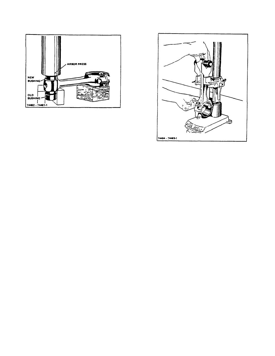
Figure 8-7. Pressing in Piston Pin Bushing |
|
||
| ||||||||||
|
|
 TM 10-3930-644-14&P
Figure 8-7. Pressing in Piston Pin Bushing
Inspect connecting rod bearing shells for scoring,
discard bearing shells if any of these conditions are
apparent. Back of bearing shells should be inspected for
bright spots and discarded if any are found, as this
Figure 8-8. Checking Connecting Rod for Twist and
condition indicates they have been moving in their
Alignment
supports.
very easily, and can be tapped through the connecting
Inspect bearing shells for wear.
Specified inside
rod and into place without distorting the piston.
diameter of bearing shells when installed with bearing
cap retaining bolts tightened to specified torque is
For each piston, first install one of the piston pin retainer
2.1870" to 2.1865". This provides a running clearance of
rings, next heat the piston, and then Insert the piston pin
.0006" to .0022", new bearing shells must be installed
and install the other retainer ring.
when this clearance exceeds .0032". Refer to TOPIC 6,
paragraph D.
BEARING INSPECTION AND
Pistons are cam and taper ground, and this must be
INSTALLATION.
and measure the connecting rod
taken into consideration when checking alignment of the
bearings for wear and clearance with the crankshaft in a
assembly, since the diameter in line with the piston pin
similar manner If crankshaft is worn or damaged and
would be less at the top of the skirt than at the bottom.
must be reground, bearing shells of .002", .010", .020"
and .040" undersize, are available.
NOTE
Ring lands at top of piston are
G. PISTON AND ROD ALIGNMENT
smaller than skirt; therefore, check
alignment of rod along full length of
The piston pin hole in the connecting rod must be
skirt only.
parallel to, and in plane with, the large bore in the
bearing end of the connecting rod.
Regardless of the preliminary check made on the
connecting rod, the completed piston and rod assembly
Alignment may be checked on a fixture with the Piston
(Figure 8-9) must be rechecked and there must not be
pin assembled in the rod before assembling the piston
more than .002" twist or out of squareness checked over
(Figure 8-8). The connecting rod may be found twisted
a spread of approximately 4 inches. The connecting rod
or bent out of alignment due to wear on the rod bushings
can be bent or twisted with a bending bar to meet this
or bearings. In this case, the rod may be carefully
specification.
straightened with a bending bar.
The snap rings must be assembled in the grooves,
Assemble the pistons on the connecting rod by first
making sure they are fully seated in place.
heating them in some form of oven or in hot water to a
minimum temperature of 160F. When heated, the
piston pin enters the piston.
R-104-1
3-30
|
|
Privacy Statement - Press Release - Copyright Information. - Contact Us |
