 |
|||
|
|
|||
|
|
|||
| ||||||||||
|
|
 TM 10-3930-644-14&P
DRIVE AXLE
TOPIC 1. DRIVE AXLE
A. DESCRIPTION
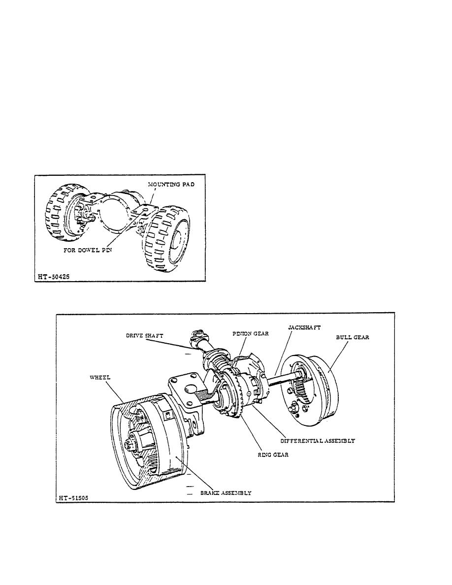
the axle shafts serve only to drive the wheels.
The drive unit is a double reduction, internal gear drive
The differential is of the bevel gear and pinion type with
within wheel, and a spiral bevel in axle housing. The
the final drive reduction through the axle shafts
drive wheels are mounted on an axle housing spindle by
(jackshaft) and bull gears (Figure 2), setting each drive
two opposed tapered roller bearings, locked in correct
wheel into motion. In order to hold the differential
adjustment by a washer, a castellated nut and cotter pin.
assembly rigidly in place in the housing, it is mounted on
The weight of the truck is carried by the axle housing,
two studs and then held firmly in position by self-locking
and through the wheels (See Figure 1); therefore, the
cap screws.
The axle shafts (jackshaft) are splined to the differential
side gears at one end and mesh with the bull gear in the
drive wheel at the opposite end. The axle shaft teeth are
crown-shaved to ensure proper meshing with the bull
gear. The axle shafts rotate at the drive wheel end in
two opposed tapered roller bearings, which are locked in
place on the shafts by a sleeve type nut and spider lock
ring. The assembly is locked in position in the axle
housing by a bearing cap and capscrews.
The bull gear is correctly located in the drive wheel by
roll pins and is bolted into the wheel from the outside so
that tightness can be checked periodically without the
necessity of removing the wheel.
Figure 1. Drive Axle Assembly (Typical)
Figure 2. Drive Unit Components (Typical)
2-63
|
|
Privacy Statement - Press Release - Copyright Information. - Contact Us |