 |
|||
|
|
|||
|
|
|||
| ||||||||||
|
|
 TM 10-3930-644-14&P
B. DRIVE UNIT SERVICE
NOTE
For service instructions on the drive
unit assembly, refer to DRIVE UNIT
should be inspected and serviced at periodic intervals.
DISASSEMBLY.
All parts should be checked for any possible damage or
excessive wear. The level of the oil in the differential
housing should be checked, and also changed when
specified.
The housing breathers should be kept clean and open to
prevent any pressure from building up in the unit.
NOTE
Refer to the LUBRICATION AND
SERVICE
GUIDE
for
specific
instructions regarding lubrication of
the drive unit.
The drive unit can
be removed as an assembly, if
desired. It will be
necessary to remove the mast
assembly min order
to remove the drive unit. The
following procedure
is recommended for drive unit
removal:
1. Removal
a. After the mast has been removed (see
LAST REMOVAL), disconnect the main
hydraulic brake line at the junction block
located on the differential housing.
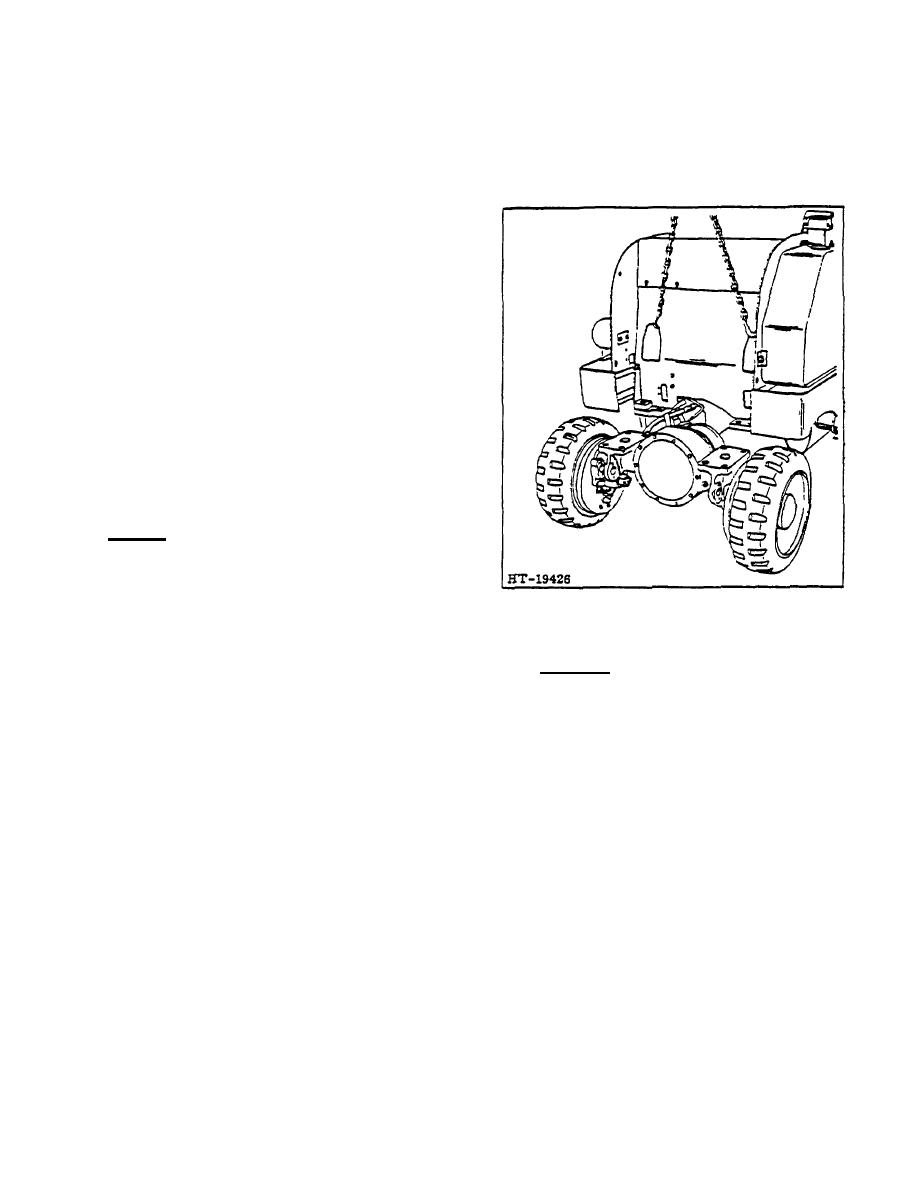
Figure 3. Drive Unit Removal
Disconnect the hydraulic lines, the
leakage return line, or any other lines
2. Installation
which are attached to the drive unit
housing.
a. To replace the drive unit assembly, carefully
b. Disconnect the emergency brake cable by
raise the truck body high enough with hoisting
removing the clevis pin from the parking
chain to position drive unit under front end at
brake actuating lever.
dowel pin location.
c. Disconnect the universal joint (see U-
b. Lower truck frame until it is securely supported
JOINTS), leaving slip joint in the
at the mounting pads and insert all mounting
transmission.
bolts and capscrews previously removed.
d. See Figure 3 and attach hoist chain hooks
c. Connect universal joint and ensure that drive
in the tilt cylinder holes in the front plate.
shaft coupling is properly aligned. (Refer to
Pull chain snug to take the weight of the
TRANSMISSION
for
proper
alignment
truck off drive axle.
procedure.)
e. Remove all mounting bolts and capscrews
d. Connect the emergency brake cable by
from mounting pads.
replacing the clevis pin at actuating level.
f. Raise the truck away from the drive unit
e. Securely tighten all mounting hardware and
and remove drive unit from under the truck
hose connections and bleed the hydraulic brake
frame. It may be necessary to apply
system. (Refer to HYDRAULIC BRAKE Section
pressure at the mounting pads in order to
for proper procedure.)
free the drive unit from the truck, because
f. Replace the mast assembly. (Refer to MAST
of the tight fit of the dowel pins in the
ASSEMBLY Section.)
mounting pads.
2-64
|
|
Privacy Statement - Press Release - Copyright Information. - Contact Us |
