 |
|||
|
|
|||
|
|
|||
| ||||||||||
|
|
 TM 10-3930-638-24&P
2-24. LIGHT SYSTEMS TROUBLESHOOTING
MALFUNCTION
TEST OR INSPECTION
CORRECTIVE ACTION
1. FRONT FLOOD LIGHTS INOPERATIVE
NOTE
If one or more front flood light operates normally, replace bulb in affected
flood light (para 2-30a). If flood light is still inoperative, check for open
circuit in wire between inoperative flood light and FRONT FLOOD switch.
Step 1.
Turn IGNITION switch to OFF and remove key.
Disconnect 10 ampere circuit breaker wire from terminal on FRONT FLOOD switch.
Connect ohmmeter leads to leads of 10 ampere circuit breaker.
a. If ohmmeter indicates less than 0.1 ohm, proceed to step 2.
b. If ohmmeter indicates more than 0.1 ohm, connect ohmmeter leads to vehicle ground and 4-wire
terminal of FRONT FLOOD switch. If ohmmeter indicates less than 2 ohms, check for short
in wiring between FRONT FLOOD switch and front flood lights. Replace 10 ampere circuit
breaker after short is removed (para 2-28a).
Step 2. Connect ohmmeter leads to terminals of FRONT FLOOD switch and set FRONT FLOOD switch at
ON position.
a. If ohmmeter indicates less than 0.1 ohm, reconnect lead of 10 ampere circuit breaker to
terminal of FRONT FLOOD switch and proceed to step 3.
b. If ohmmeter indicates more than 0.1 ohm, replace FRONT FLOOD switch (para 2-28a).
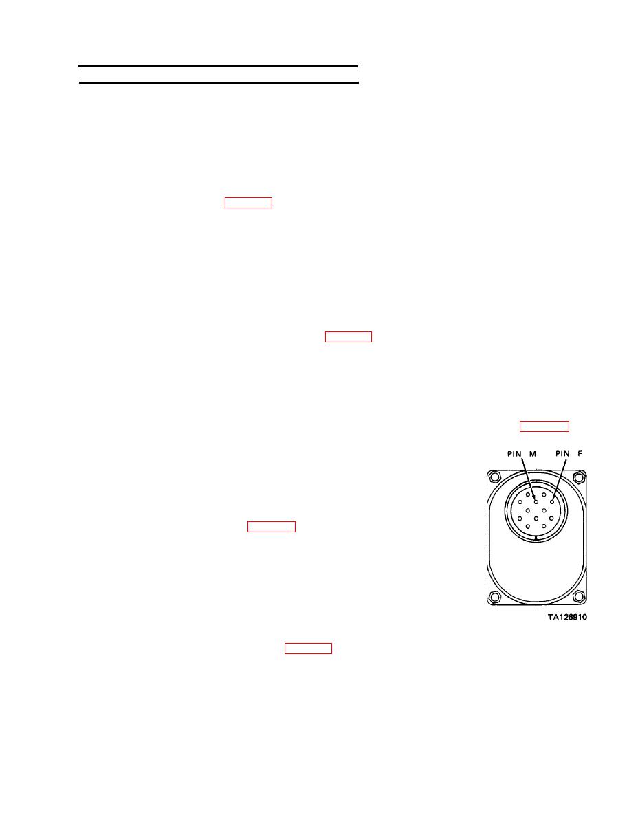
Unscrew and remove cable connector from bottom of VEHICLE
Step 3.
LIGHTS switch.
Place main switch lever on VEHICLE LIGHTS switch in SER.
DRIVE position.
Connect ohmmeter leads to pins F and M of VEHICLE LIGHTS switch.
If ohmmeter indicates more than 0.1 ohm, replace VEHICLE
LIGHTS switch (para 2-28b).
2. FRONT BLACK OUT LIGHT INOPERATIVE
Unplug wire connector from front black out terminal. Set IGNITION
Step 1.
switch to ON position and place main switch lever on VEHICLE
LIGHTS switch in B.O. DRIVE position.
Connect positive voltmeter lead to vehicle ground.
a. If voltmeter indicates 24 Vdc, place IGNITION switch and
VEHICLE LIGHTS switch in OFF position and place bulb in
front black out light (para 2-30b).
b. If voltmeter does not indicate 24 Vdc, place IGNITION switch in
OFF position. reconnect wire connector to terminal on front
black out light, and proceed to step 2.
|
|
Privacy Statement - Press Release - Copyright Information. - Contact Us |
