 |
|||
|
|
|||
|
|
|||
| ||||||||||
|
|
 TM 10-3930-638-24&P
2-23. HORN AND BACK-UP ALARM SYSTEM TROUBLESHOOTING (cont)
MALFUNCTION
TEST OR INSPECTION
CORRECTIVE ACTION
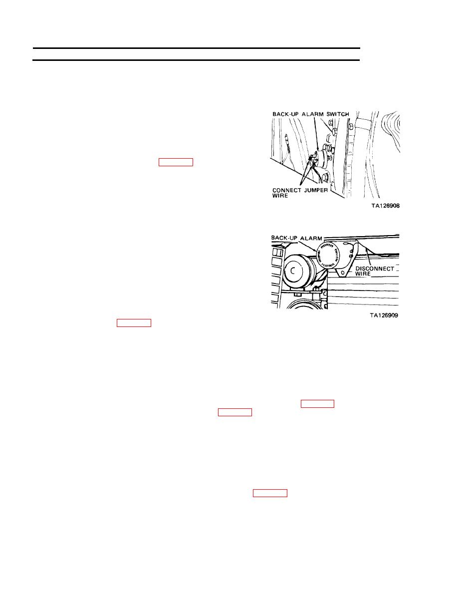
2. BACK-UP ALARM DOES NOT SOUND
Step 1. Turn IGNITION switch key to ON position and
temporarily connect a jumper wire to terminals of
back-up alarm switch.
a. If back-up alarm sounds, replace back-up
alarm switch (para 2-31b).
b. If back-up alarm does not sound, proceed
to step 2.
Step 2. Disconnect wire from positive terminals of back-up
alarm.
Temporarily connect a jumper wire between positive
battery cable and positive terminal of back-up
alarm.
a. If back-up alarm sounds, reconnect wire to
positive alarm terminal and proceed to step 3.
b. If back-up alarm does not sound, connect a
jumper wire to vehicle ground and back-up
alarm negative terminal. If alarm does not
sound with ground jumper at negative
terminal and battery positive jumper at
positive terminal, replace back-up alarm
Step 3. Turn and hold IGNITION switch key at LAMP TEST position.
a. If at least one warning indicator (TRANSMISSION TEMPERATURE, HYDRAULIC
FILTER, or ENGINE TEMPERATURE) is on, check for open circuit in wiring between
back-up alarm, back-up alarm switch, and 6 ampere circuit breaker.
b. If at least one warning indicator is not on, turn IGNITION switch key to ON position and
check if a slight buzz can be heard at electric fuel pump. If slight buzz indicating electric fuel
pump operation is not heard, troubleshoot IGNITION switch (para 2-25). If slight buzz is heard,
troubleshoot warning indicators (para 2-25).
NOTE
If flood lights, tail lights, stop lights and gage lights are all inoperative, turn
IGNITION switch key to OFF position. Connect positive voltmeter lead to
terminal F of VEHICLE LIGHTS switch cable connector and negative
voltmeter lead to vehicle ground. If voltmeter does not indicate 24 Vdc with
IGNITION switch key set at ON position, check for open circuit in wiring
between terminal F of cable connector and IGNITION switch. If wiring
check is satisfactory, replace IGNITION switch (para 2-28c).
|
|
Privacy Statement - Press Release - Copyright Information. - Contact Us |
