 |
|||
|
|
|||
|
Page Title:
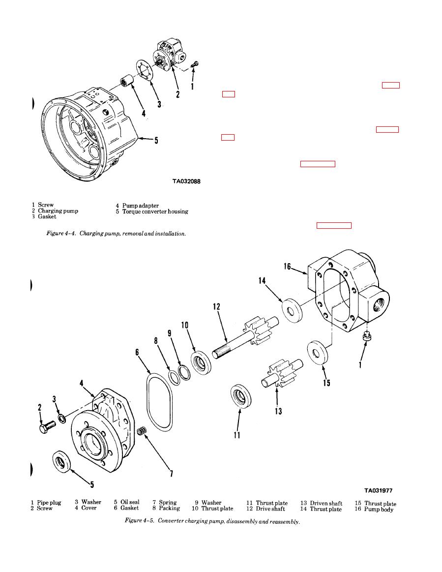
Figure 4-4. Charging pump, removal and installation |
|
||
| ||||||||||
|
|
 TM 10-3930-634-34
elements operate in oil which is circulated for cooling.
When the engine rotates, oil is thrown by the impeller
blades into the blades of the turbine causing the tur-
bine to rotate.
b. Removal.
(1) Remove the torque converter assembly (para
( 2 ) Clean exterior of torque converter housing
thoroughly using cleaning solvent P-D-680.
(3) Remove 24 screw-assembled-washers securing
the impeller cover to the impeller as shown in figure
4-6, A.
(4) Install two of the screw assemblies removed in
(3) above in the two threaded holes provided in the im-
peller cover as shown in figure 4-6, B, to act as jacking
s c r e w s . Holes are 180 apart. Turning the jacking
screws in will separate the impeller cover from the im-
peller. Carefully lift the impeller cover from the con-
verter housing so as not to damage the cover needle
bearing.
(5) Remove turbine retaining ring and the turbine
and hub assembly as shown in figure 4-7. After tur-
bine and hub assembly is removed, remove the turbine
|
|
Privacy Statement - Press Release - Copyright Information. - Contact Us |