 |
|||
|
|
|||
|
Page Title:
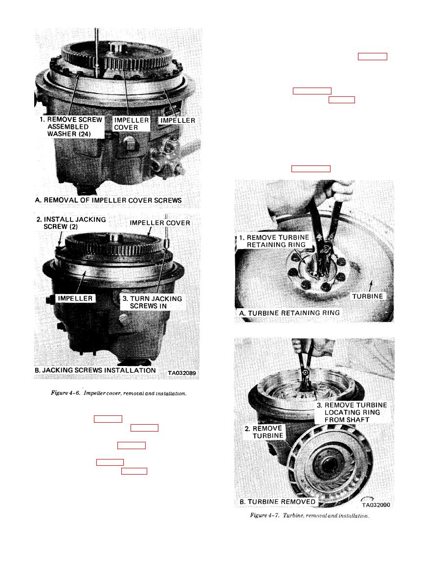
Figure 4-7. Turbine, removal and installation |
|
||
| ||||||||||
|
|
 TM 10-3930-634-34
and gasket (10). Remove retaining ring (11) and pump
drive sleeve (12).
(10) Remove three pump drive shafts (fig. 4-20).
c. Disassembly.
(1) Stator Support.
(a) Disassemble the stator support in numerical
sequence as shown in figure 4-21.
move turbine shaft spur gear (2).
(c) Remove retaining ring (3) and press turbine
shaft (4) from stator support (8). Press turbine ball
bearing (5) from turbine shaft.
(d) Remove turbine shaft piston rings (6 and 7).
(2) Output Shaft.
(a) Disassemble the output shaft in numerics
sequence as shown in figure 4-22.
(4) Remove impeller and oil baffle from torque
converter assembly (para 4-4).
(5) Remove stator support (fig. 4-16).
(6) Remove output flange cotter pin, nut, washer,
packing, and output flange (fig. 4-17).
(7) Remove bearing retainer, output shaft and
ear as an assembly (fig. 4-18).
(8) Remove six nuts (1, fig. 4-19), and washers (2)
securing pump adapter (3) to converter housing (13).
Remove pump adapter and gasket (4). Remove retain-
ing ring (5) and pump drive sleeve (6).
(9) Remove three screws (7) and washers (8), se-
curing pump adapter (9) and remove pump adapter
|
|
Privacy Statement - Press Release - Copyright Information. - Contact Us |