 |
|||
|
|
|||
|
Page Title:
Camshaft, Balance Shaft and Bearings |
|
||
| ||||||||||
|
|
 TM 10-3930-634-34
assembly is installed in the cylinder liner.
connecting rod (12).
(b) Install the top oil ring, with the gap 180
(3) Use a suitable ring compressor and apply clean
the ends of the expander, in the piston upper oil
engine oil to the piston rings and the inside of the ring
ring groove. Install the bottom oil ring with the gap
compressor.
(4) Start the skirt of the piston into the cylinder
45 from the top oil ring gap. Recheck to make sure
block and lightly tap the top of the piston into the
the ends of the expanders are not overlapped.
CAUTION
block with the wooden handle of a hammer until it
Do not at any time, cut off or grind the ends
clears the ring compressor. Pull the piston and rod
of the oil ring expander to prevent the ends
assembly down until the upper bearing half seats
from overlapping. This will decrease the
firmly on the crankshaft journal.
tension on the oil control rings and result in
(5) Place the lower bearing half (4, fig. 3-109) in
high oil consumption.
the connecting rod cap (3) and lubricate the bearing
(c) Install the second set of oil rings in a similar
with clean engine oil,
manner.
(6) Note the identifying marks on the bearing cap
(6) Refer to figure 3-117 for proper ring location
and the rod and assemble the cap to the rod as
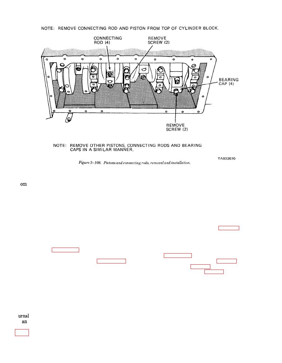
illustrated in figure 3-108.
and install the four compression rings on the piston
(7) Install oil inlet tube and screen (para 3-27).
using a ring expander as illustrated in figure 3-110.
Stagger the ring gaps around the piston. Do not spread
(8) Install the oil pan (para 3-26).
rings more than necessary to install on piston.
(9) Install the cylinder head (para 3-25).
NOTE
When installing the top compression (fire)
3-35. Camshaft, Balance Shaft and Bear-
ring with the tapered face, be sure and install
ings
the ring with the mark "TOP" toward the top
a. General.
of the. piston.
.
(1) The camshaft and balance shaft are located
g. Installation.
just below the top of the cylinder block. The shafts are
(1) Rotate the crankshaft until the connecting rod
supported by bearings that are pressed into bores in
is at the bottom of its travel. Wipe the journal
the cylinder block. The balance shaft is supported by
and lubricate it with clean engine oil.
front and rear bearings. The camshaft is supported by
(2) Install the two connecting rod bolts (2, fig.
end, intermediate, and center bearings.
|
|
Privacy Statement - Press Release - Copyright Information. - Contact Us |