 |
|||
|
|
|||
|
|
|||
| ||||||||||
|
|
 TM 10-3930-634-34
(15) Make sure the flywheel housing is supported
adequately with a sling and hoists.
(16) Strike the front face of the flywheel housing
(12) alternately on each side of the engine with a soft
hammer to loosen and work it off dowel pins.
(17) Remove shim (13) and gasket (14).
c. Disassembly.
(1) Disassemble the flywheel housing in numerical
sequence as shown in figure 3-101.
(2) Drive oil seal (28, fig. 3-101) from housing (12)
with a suitable drift.
d. Cleaning and Inspection.
(1) Clean all parts thoroughly with cleaning sol-
vent P-D-680 and dry thoroughly.
(2) Clean all traces of gasket material from fly-
wheel housing and end plate.
(3) Inspect the flywheel housing for cracks or
other damage. Replace a damaged flywheel housing.
( 4 ) Inspect all threaded parts for damaged
threads. Replace parts that have damaged threads.
e. Reassembly.
(1) Install new oil seal in the flywheel housing
(2) Install new gasket (14, fig 3-101) on the rear
face of the cylinder block end plate.
housing bore.
(3) Install shim (13) on the left side of the engine.
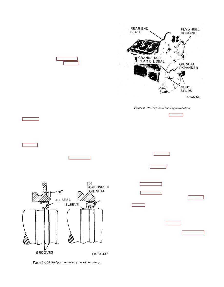
(2) If the rear seal contact area on the crankshaft
Use grease to hold shim in place until the flywheel
is grooved from excessive wear, the seal may be
housing is installed.
pressed into the flywheel housing 1/8 inch from its origi-
(4) Coat the lip of the crankshaft seal (28) lightly
nal position or install an oil seal sleeve as shown in fig-
with grease. Do not scratch or nick the sealing edge of
the seal.
seal sleeve is used.
(5) Use proper seal expander to aid in piloting the
(3) Reassemble the flywheel housing in reverse
seal on the crankshaft (fig. 3-105).
numerical sequence shown in figure 3-101.
(6) With the housing suitably supported, position
f. Installation.
it over the crankshaft and up against the cylinder
(1) Lubricate the gear train teeth with clean en-
block rear end plate (fig. 3-105).
gine oil.
(7) Install the screws, lockwashers and selflocking
screws in the same locations they were removed from.
Tighten finger tight.
(8) Using figure 3-106, A, tighten the capscrews
and self-locking screws snug in the sequence shown.
(9) Using figure 3-106, B, tighten the capscrews
in the sequence shown to the values listed in table 3-1.
Torque (lb-ft.)
Screw No. (fig. 3-106)
40-45
7 through 10
19-23
11 and 12
25-30
Remaining Screws
(10) Install the flywheel (para 3-32).
(11) Check flywheel housing concentricity with a
dual dial indicator on surfaces shown in figure 3-107.
Rotate the flywheel through one full revolution, tak-
ing readings at each 45 interval. Maximum total indi-
cator reading must not exceed 0.013 inch. If runout ex-
ceeds 0.013 inch remove flywheel housing and check
for dirt or foreign material (such as old gasket mate-
rial) between the flywheel housing and the rear end
plate.
|
|
Privacy Statement - Press Release - Copyright Information. - Contact Us |