 |
|||
|
|
|||
|
|
|||
| ||||||||||
|
|
 TM 10-3930-634-34
gear pressed on the front end of the crankshaft. The
3-30. Front Trunnion Mount
outer rotor is driven by the inner rotor. As the rotors
a. General. Thetrunnion mount secures the front of
revolve, a vacuum is formed on the inlet side of the
the engine to the forklift truck. Removal of the trun-
pump and oil is drawn from the crankcase through the
nion is with engine removed from the forklift truck.
oil pump inlet tube and a passage in the front cover, to
b. Removal.
the inlet port and then into the rotor compartment of
(1) Remove the engine (para 2-5).
the pump. Oil drawn into the cavities between the in-
(2) Remove the crankshaft pulley (para 3-29).
ner and outer rotors on the inlet side of the pump is
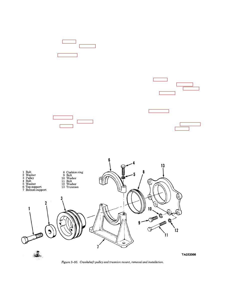
(3) Remove the front trunnion mount in numeri-
then forced out under pressure through the discharge
cal sequence as shown in figure 3-95.
port into a passage in the front cover which leads to
c. Cleaning and Inspection.
the lubricating oil filter and cooler, and is then dis-
(1) Clean all metal parts with cleaning solvent
tributed throughout the engine. The lower front cover
P-D-680 and dry thoroughly.
also carries the front crankshaft oil seal.
(2) Clean the cushion ring with a damp cloth. Dry
b. Removal.
thoroughly.
(1) Remove engine (para 2-5).
(3) Inspect the trunnion for cracks or breaks.
(2) Remove the crankshaft pulley (para 3-29).
Repair by replacement.
(3) Remove the front trunnion mount (para 3-30).
(4) Inspect the cushion ring for evidence of deter-
(4) Remove the oil pan (para 3-26).
ioration. Repair by replacement.
(5) Remove the oil inlet tube and screen (para
(5) Inspect hardware for damaged threads. Re-
3-26).
place all parts having damaged threads.
(6) Remove the lower front cover in numerical se-
d. Installation.
quence illustrated on figure 3-96.
(1) Install the front trunnion in reverse of numeri-
c. Disassembly.
cal sequence shown in figure 3-95.
(1) Disassemble the lower front cover and oil
(2) Install the crankshaft pulley (para 3-29).
pump in numerical sequence as shown in figure 3-97.
(3) Install the engine (para 2-5).
(2) Remove pump drive gear (16, fig. 3-97) only if
replacement is required. A suitable gear puller will be
3-31. Lower Front Cover and Oil Pump
required to remove the gear.
d. Cleaning and Inspection.
a. General. The lubricating oil pump is assembled to
(1) Clean all parts with cleaning solvent P-D-60
the inside of the lower engine front cover. The pump is
and dry thoroughly.
the rotor type in which the inner rotor is driven by a
|
|
Privacy Statement - Press Release - Copyright Information. - Contact Us |