 |
|||
|
|
|||
|
Page Title:
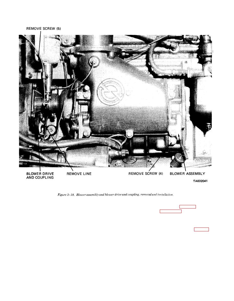
Figure 3-18. Blower assembly and blower drive and coupling |
|
||
| ||||||||||
|
|
 TM10-3930-634-34
(7) Install the air inlet housing (para 3-13).
compartment at the end plates and oil seals. A thin
film of oil radiating away from the seals indicates an
blower assembly.
oil leak is present.
d. Disassembly.
(4) With the engine running, check blower drive.
(1) Wedge a clean cloth between the rotors to pre-
A worn blower drive results in a loose, rattling sound
vent their turning, remove four screws (5, fig. 3-19)
within the blower which can be detected with the en-
and remove the drive cam retainer, springs and sup-
gine operating at approximately 500 RPM.
port (6 through 10) from the blower drive gear (20).
(5) Inspect the rotor for loose rotor shafts or worn
(2) Match mark the blower drive gear (20) so it can
bearings. Defective bearings will result in contact be-
be installed in the same position. Remove the two
tween the rotor lobes; rotors and end plates or rotors
rotor gear retaining bolts (15 and 17). Use two pullers
and housing.
and remove both blower gears from the rotor shafts at
(6) Inspect the rotor lobes for excessive backlash.
the same time.
Excessive backlash between the blower timing gears
(3) Continue disassembly in numerical order.
will result in the rotor lobes rubbing throughout their
e. Cleaning and Inspection.
entire length.
3-20
|
|
Privacy Statement - Press Release - Copyright Information. - Contact Us |