 |
|||
|
|
|||
|
Page Title:
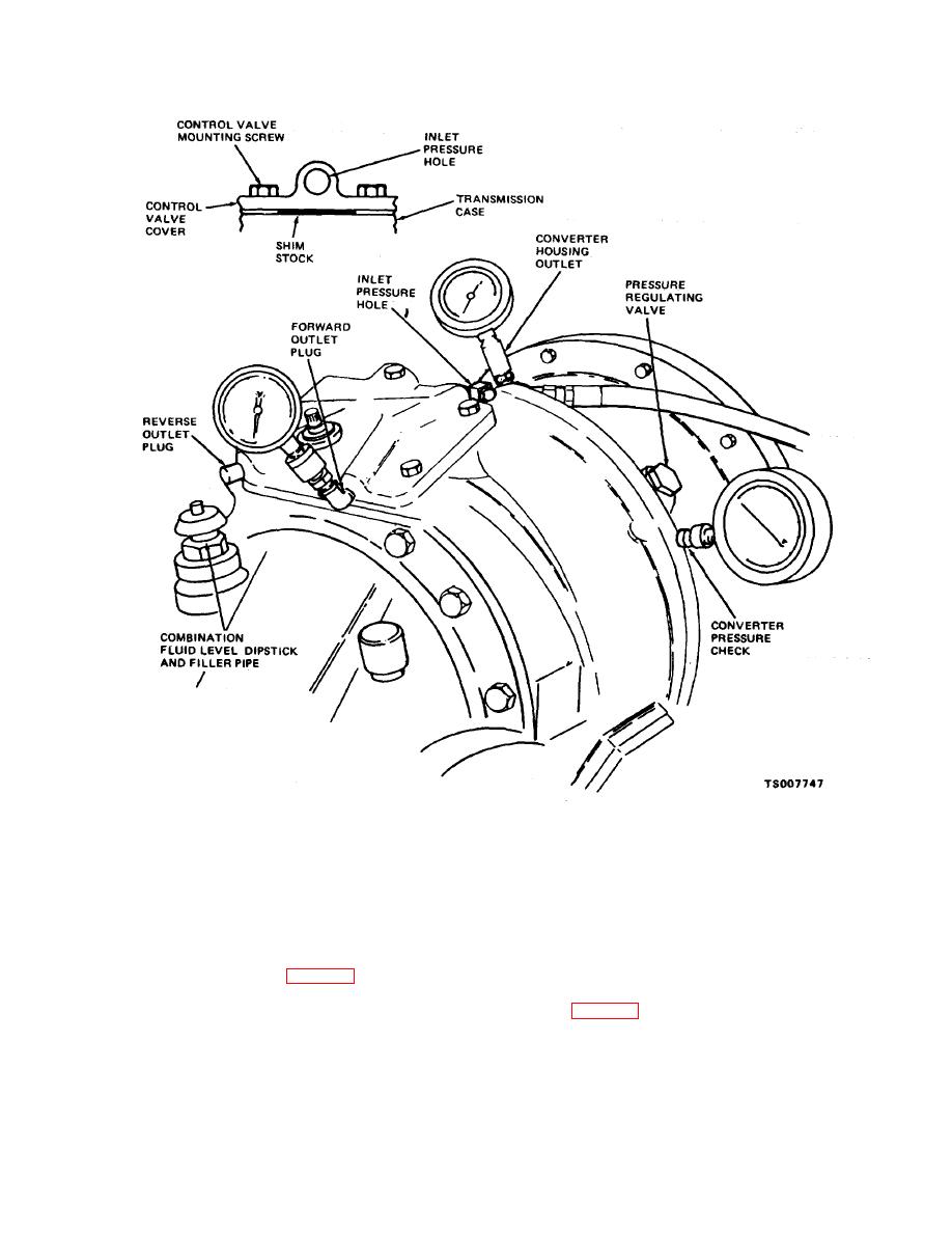
Figure 2-12. Transmission Test Setup. |
|
||
| ||||||||||
|
|
 TM 10-3930-632-34
Figure 2-12. Transmission Test Setup.
(b) Run the engine at 2000 RPM with the
(d) Remove gage from the converter housing
transmission in neutral. The pressure gage should
outlet and replace the plug.
indicate between 110 and 125 PSI. If the pressure is
(11) Check the transmission control valve and
low, loosen the control valve mounting screws and place
transmission directional assemblies as follows:
shim stock (0.001 inch to 0.002 inch thick by 11/s inches
(a) Securely block the fork lift truck so that it
wide) between the inlet pressure hole of the control valve
cannot move.
cover and the transmission case (fig. 2-12). Tighten the
(b) Install a pressure gage that indicates between
mounting screws.
0 and 200 PSI at either the forward or reverse outlet plug
(c)
Recheck the pressure as described in (a) and
positions (fig. 2-12).
(b) above. If the pressure is still low, overhaul the control
(c)
Run the engine at 2000 RPM and place the
valve pressure regulating valve or replace the
transmission control lever in the position that
transmission oil pump. Determine which is defective as
corresponds to the outlet at which the pressure gage has
described in (11) below.
been placed (forward or reverse). The
2-19
|
|
Privacy Statement - Press Release - Copyright Information. - Contact Us |