 |
|||
|
|
|||
|
|
|||
| ||||||||||
|
|
 TM 10-3930-632-12
c. Installation.
(2) Disconnect the exhaust connector from
the manifold (fig. 4-41).
(1) Install the oil filter and related parts as
(3)
Disconnect the positive crankcase
shown in figure 4-47. Use a new filter element during
ventilation piping from the intake and exhaust manifold
reassembly.
4-68. Intake and Exhaust Manifold
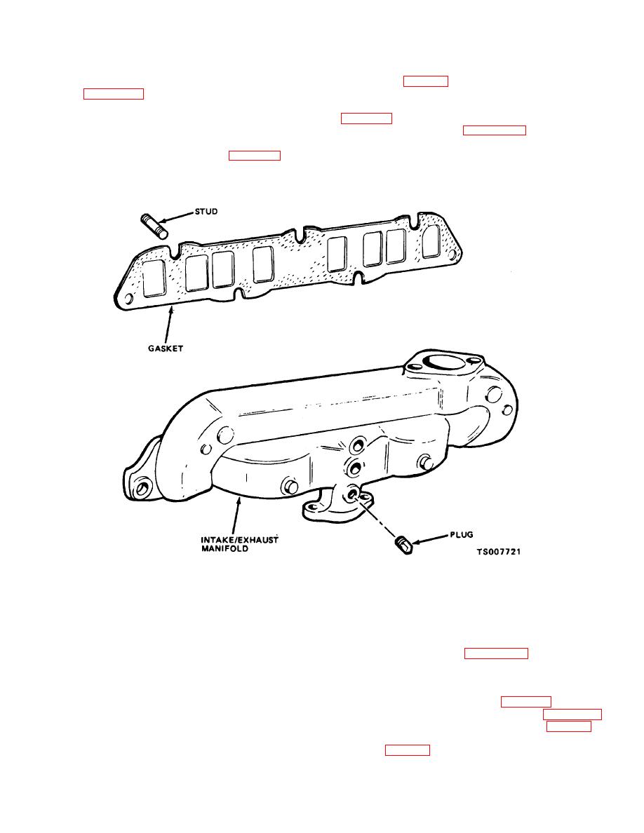
(4) Refer to figure 4-48 and remove the
a. Removal.
intake and exhaust manifold from the engine.
(1) Remove the carburetor (para 4-42) and
disconnect the air inlet hose from the air cleaner (fig. 4-
32).
Figure 4-48. Intake and Exhaust Manifold, Removal and Installation
WARNING
(3) Inspect for loose or damaged studs.
(4) Replace the gasket; replace other parts
Dry cleaning solvent, P-D-680, used to
if defective.
clean parts is potentially dangerous to
c. Installation.
personnel and property. Avoid repeated
(1) Refer to figure 4-48 and install the
and prolonged skin contact. Do not use
intake manifold, using a new gasket. Tighten the stud
near open flame of excessive heat. Flash
nuts to 25 to 30 foot-pounds.
point of solvent is 100F.-138F. (38C.-
(2)
Install the positive crankcase
60C.).
b. Cleaning and Inspection.
ventilation piping on the manifold (para 4-47).
(3)
Install the carburetor (para 4-42).
(1) Clean dirt from the manifold with a wire
Connect the air inlet hose to the air cleaner (fig. 4-32).
brush; then clean with a cloth dampened in dry cleaning
(4) Connect the exhaust connector to the
solvent P-D-680.
manifold (fig. 4-41).
(2)
Inspect the manifold for cracks,
warping, damaged sealing surfaces, corroded areas,
damaged threads, or other defects.
4-63
|
|
Privacy Statement - Press Release - Copyright Information. - Contact Us |