 |
|||
|
|
|||
|
|
|||
| ||||||||||
|
|
 TM 10-3930-631-34
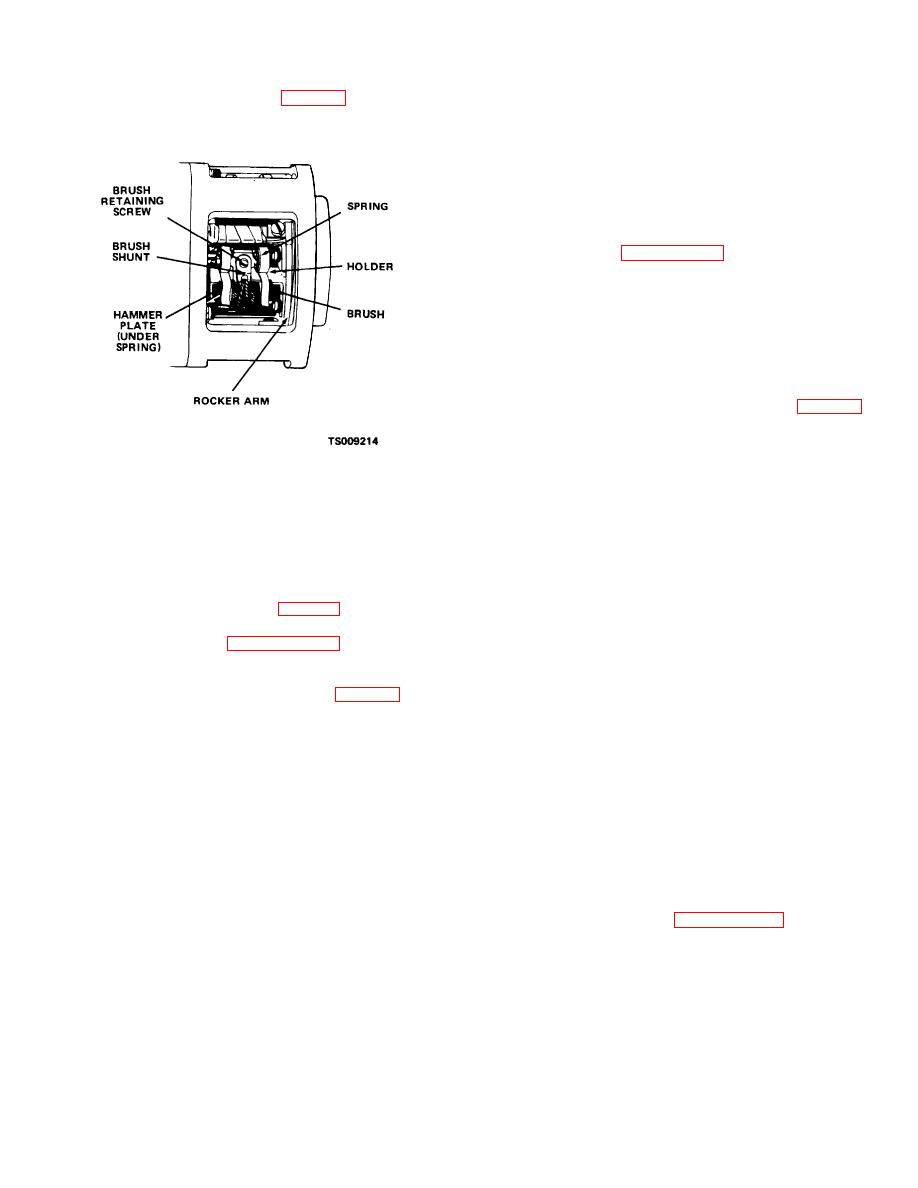
(4) Remove brush screw (fig. 8-11) and washer
housing, with attached rocker arm assembly, from motor.
and lift spring to slide brushes from brush holder.
(6) Remove nuts, washers and insulators and
remove studs from housing.
(7) Remove screws (21) and lock washers (22)
and remove rocker arm assembly from rear housing.
Press bearing (20) from rear housing.
(8) Remove pole shoe screws (40) and remove
pole shoes (41) and field winding (42) from housing.
d. Cleaning, Inspection and Repair.
(1) Refer to paragraph 8-2 d. and clean, inspect
and repair the hydraulic pump motor in the same
manner.
(2) Inspect fan for damage to blades and wear
in shaft diameter. Replace unserviceable fans.
(3) Inspect mounting brackets for bent or
damaged condition. Straighten brackets if possible.
Replace damaged brackets.
e. Assembly.
(1) Install terminal studs (36 and 38, fig. 8- 10)
in housing and torque studs to 107 pound- inches (.92
m-kg). Install nuts, washers and insulators.
(2) Install field windings (42) and pole shoes
(41) in housing and secure with pole shoe screws (40).
Figure 8-11. Hydraulic pump motor brush location.
CAUTION
Handle field windings carefully to avoid damage
(5) Refer to paragraph 8-2a. steps (4) through
to insulation.
(12) and replace brushes.
(3) Fill bearing (20) half full of grease (GAA) and
Note
press into rear housing (29). Install rocker arm assembly
In step (11) brush spring pressure should be 25
(27) on rear housing and secure with screws (21) and
ounce, (0.695 kg).
lock washers (22).
(6) Install rear cover (13, fig. 8-10) on motor.
(4) Move rear housing (29) into position and
(7) Install drip pan.
connect leads (31, 32, and 33) to rocker arms and field
b. Removal. Refer to paragraph 2-13 and
windings. Install rear housing and bracket (11) and
remove pump motor.
secure with screws (7 and 10) and lock washers (8).
c. Disassembly.
(5) Install key (18) in slot in shaft. Heat fan (17)
(1) Remove screws (6, 7, and 10, fig. 8-10) and
in oven to 200F (93C) and press fan into place over
lock washers (8) and remove brackets (9 and 11) from
key.
motor.
(6) Press bearings (15 and 20) on armature
(2) Remove front and rear covers (12 and 13)
shaft.
from motor. Refer to a. above and remove brushes.
(7) Place assembled housing (43) in a vertical
(3) Remove remaining screws and remove front
position and carefully lower armature assembly into
housing (14) from motor. Carefully remove armature
position in bearings. Install armature carefully to avoid
assembly, with attached bearings and fan, from motor
damage to commutator and field windings.
housing.
(8) Position front housing (14) and bracket (9)
CAUTION
on motor and secure with screws (6 and 7) lock washers
Use care when removing armature to prevent
(8).
damage to commutator, core and pole faces.
(9) Refer to a. above and install brushes in
Remove armature by lifting straight up out of
pump motor.
housing.
f. Installation. Refer to paragraph 2-13 and
(4) Use a suitable puller and remove bearings
install pump motor.
(15 and 20) from armature shaft. Remove fan (17) and
key (18) from shaft.
(5) Remove remaining screws and remove rear
housing (29) far enough to disconnect leads from rocker
arms and studs. Remove rear
8-8
|
|
Privacy Statement - Press Release - Copyright Information. - Contact Us |
