 |
|||
|
|
|||
|
|
|||
| ||||||||||
|
|
 TM 10-3930-631-34
b. Installation.
(4) Remove plugs from pump and hoses and
connect hoses to pump.
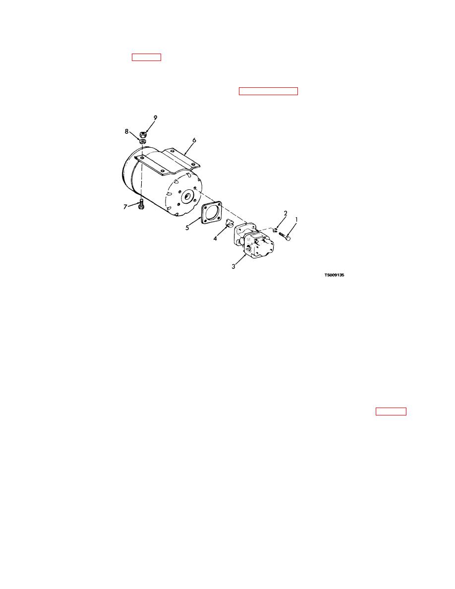
(1) Install coupling (4, fig. 2-2) and gasket (5)
(5) Check hydraulic reservoir and fill to proper
on pump and motor. Install pump in position on motor
level if necessary.
and secure with screws (1) and lock washers (2).
(6) Connect battery receptacle.
Refer to
(2) Install pump and motor on truck frame and
Adjust
secure with screws, lock washers, and nuts. (3) Check
pressure if necessary.
tags on electrical leads and connect to electric motor.
1.
Screw
2.
Lock washer
3.
Pump
4.
Coupling
5.
Gasket
6.
Motor
7.
Screw
8.
Lock washer
9.
Nut
Figure 2-2. Steering hydraulic motor and pump.
(1) Remove floor and toe plates to gain access
2-12. Steering Valve Unit
to steering valve.
a. Removal.
(2) Tag and disconnect hoses (fig. 2-3) from
CAUTION
steering valve. Plug or cap ports in steering valve and
Before proceeding with removal procedures,
ends of hoses to prevent entrance of foreign matter.
disconnect battery receptacle and discharge
capacitors.
2-7
|
|
Privacy Statement - Press Release - Copyright Information. - Contact Us |