 |
|||
|
|
|||
|
Page Title:
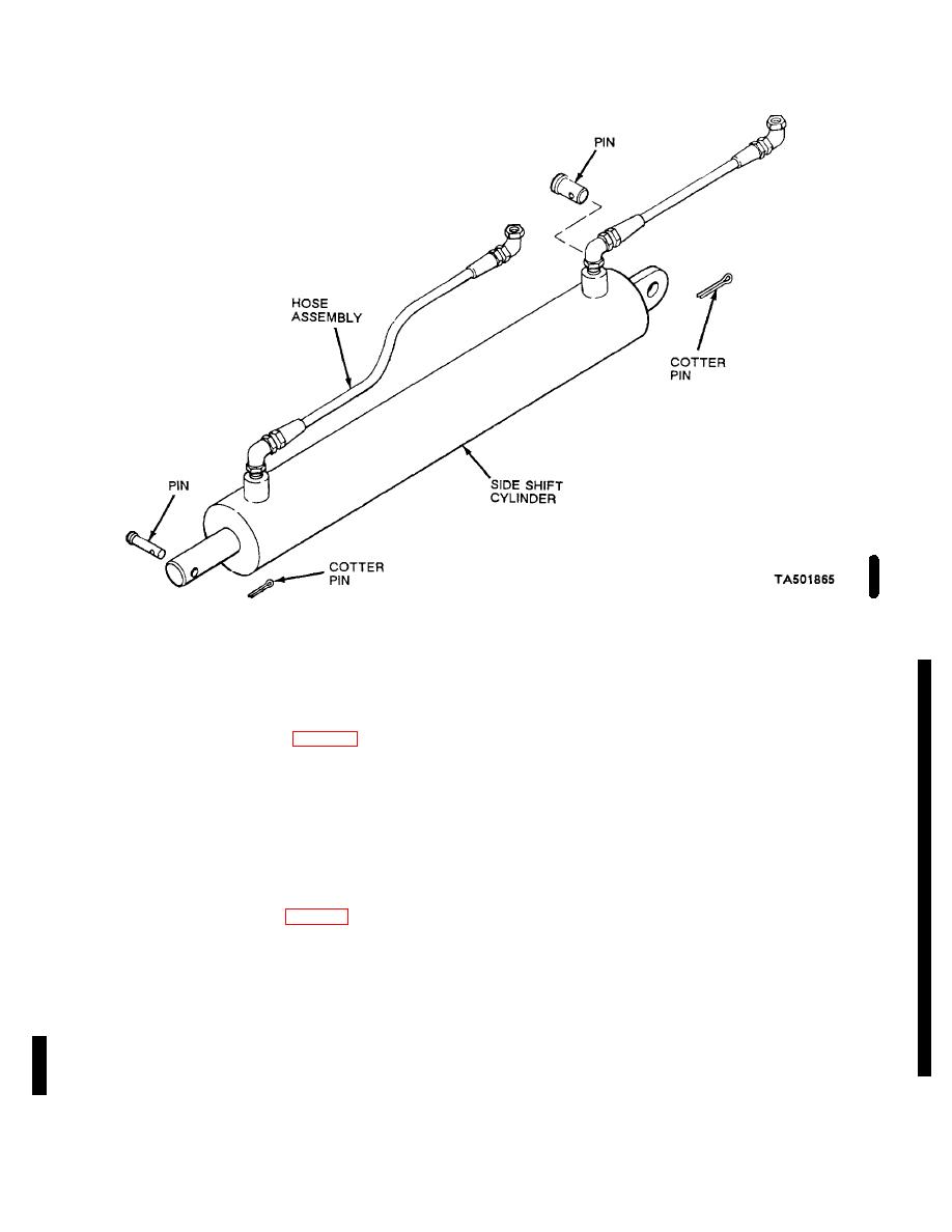
Figure 4-44. Side shift cylinder, exploded view. |
|
||
| ||||||||||
|
|
 TM 10-3930-631-12
Figure 4-44. Side shift cylinder, exploded view.
(3) Remove cotter pins and cylinder pins
(2)
Work through cutout in drum and
from both ends of cylinder and remove cylinder from
remove setscrew (11) and pin (12) and disengage shaft
carriage.
from shaft extension. Remove retaining ring (13) and
b. Installation.
washer (14). Remove shaft from swivel.
(3) Remove pin (15) from shaft. Remove
(1) Install cylinder (fig. 4-44) on carriage
backup rings (16) and packings (17) from shaft (27).
with ends of cylinder in line with mounting brackets.
Discard backup rings and packing.
(2) Secure cylinder to carriage with cylinder
(4) Remove nuts (18) and separate swivel
pins and cotter pins.
(19) and drum (20). Remove cover (21) from spring and
(3) Remove plugs or caps from cylinder and
cup (26).
hoses and connect hoses to cylinder.
(5) Remove pin (22) and disengage shaft
(4)
Operate side shift mechanism and
extension (23) from hub (24). Remove hub and spring
check hoses and cylinder for leaks.
(25) from cup (26).
4-58. Side Shift Hose Reel
c. Cleaning, Inspection and Repair.
a. Removal.
WARNING
(1) Unreel hoses (1, fig. 4-45) from reel (2)
Cleaning compound, solvent (Fed.
Disconnect hoses from fittings at end of reel and from
Spec. P-D-680), used for cleaning, is
junction block (3) inside reel. Cap or plug hoses to
potentially dangerous to personnel and
prevent entrance of foreign matter.
property. Do not use near open flame.
(2) Remove two long screws (4) and lock
Flash point of solvent is 1000F to 1380F
washers (5) securing hose reel to mounting block (6) on
(380C to 590C).
inner mast.
b. Disassembly.
(1)
Clean all metal parts in cleaning
compound, solvent (Fed. Spec. P-D-680) and dry
(1)
Remove two screws (7) and lock
thoroughly.
washers (8) and remove swivel block (9) from reel.
Remove packings (10).
Change 2 4-51
|
|
Privacy Statement - Press Release - Copyright Information. - Contact Us |