 |
|||
|
|
|||
|
|
|||
| ||||||||||
|
|
 TM 10-3930-631-12
c. Cleaning and Inspection.
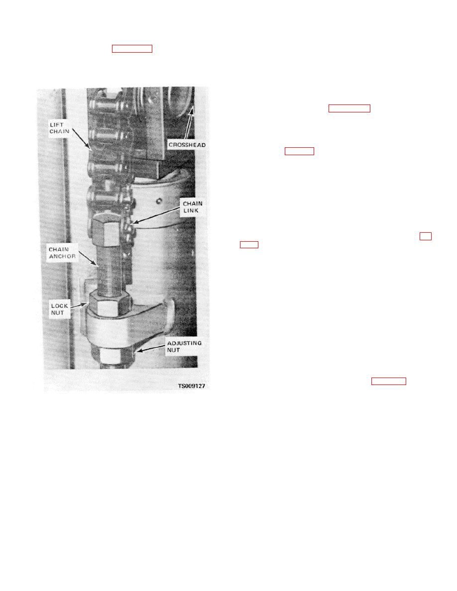
(4) Refer to figure 4-43 and remove cotter
pins and chain links from chain anchors attached to the
(1) Clean chains with cleaning compound,
cluster cylinder. Lift chains over chain bearings and off
solvent (Fed. Spec. P-D-680) and dry thoroughly.
of cross head and remove chains From mast.
(2) Inspect chains for bent, cracked, or
damaged links. Replace defective links.
(3) Lubricate chains with oil IOE).
d. Installation.
(1) Refer to figure 4-43 and place chains
through cross heads and around chain bearings.
(2) Connect chains to chain anchors with
chain links and cotter pins.
(3) Lower other ends of chains to anchors
on carriage (fig. 4-42) and attach chains to anchors with
chain links and cotter pins.
(4)
Operate lift mechanism and check
chains for bending or uneven operation. If cylinder
cluster is fully retracted, carriage should be level and
forks should not touch floor. Refer to e below to adjust
chains.
e. Chain Adjustment.
(1) Check to see that mast is in a vertical
position and that cylinder cluster is fully retracted.
(2) Loosen locknuts and adjusting nuts (fig.
(3) Turn the adjusting nuts to vary chain
length. Tighten or loosen the chains until the chains are
a snug fit and forks barely clear the floor.
(4) Tension must be equal on both chains
and carriage must be level.
(5) Tighten locknuts. Check adjustment to
see it has not been disturbed.
(6) Operate lift mechanism and check chain
operation.
(7) Lower carriage and fully retract cylinder
cluster. Check for carriage level and forks clearing floor.
4-57. Side Shift Cylinder
a. Removal.
(1) Lower carriage and forks to ground.
Shift carriage to center position. Shut off truck.
(2) Disconnect hoses (fig. 4-44) from
fittings in cylinder. Cap or plug hoses and fittings to
prevent entrance of foreign matter.
Figure 4-43. Lift chains and chain anchors,
installed view.
4-50
|
|
Privacy Statement - Press Release - Copyright Information. - Contact Us |