 |
|||
|
|
|||
|
Page Title:
Piston and Connecting Rod, Reassembly and Installation |
|
||
| ||||||||||
|
|
 TM 10-3930-630-34
(3) Install connecting rod bearing shells (10,
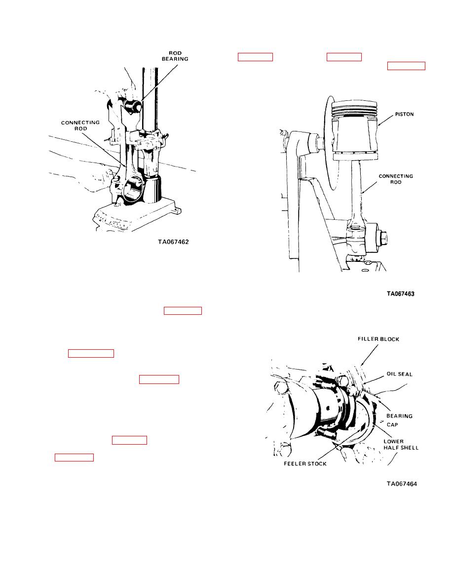
(4) Install a piece of feeler stock (fig. 11-24)
0.0005 inch (0.012 mm) thick across connecting rod
bearing shell.
Figure 11-22. Checking connecting rod alignment.
(6) Straighten rod if possible.
Replace
excessively bent or twisted rods.
(7) Remove piston pin front connecting rod.
Heat piston in oven to a minimum temperature of 160 F
Figure 11-23. Checking connecting rod and piston.
(71 C). Install one retaining ring (2, fig. 11-18) in
piston. Install piston (4) on connecting rod (6) and slide
piston pin (3) through piston and rod.
Secure pin with two remaining retaining rings (8).
(8) Place assembled piston and rod in fixture
as shown in figure 11-23. Check alignment. Piston and
rod must not be more than 0.002 inch (0.05 mm) out of
square checked over a spread of four inches.
(9) Remove cap nuts (7, fig. 11-18), cap bolts
(8), bearing caps (9) and bearing shells (10) from
connecting rod.
11-19. Piston and Connecting Rod, Reassembly
and Installation
(1) Use a piston ring installer and install piston
rings (1, fig. 11-18) in correct grooves on piston.
(2) Check to see that piston is securely
attached to connecting rod and that both retaining rings
(2) are installed.
b. Installation.
Figure 11-24. Checking connecting rod bearing
(1) Coat piston and rings with oil (OE/HDO).
clearance with feeler gage stock.
(2) Use a piston ring compressor and install
assembled piston and rod into proper cylinder through
top of cylinder bore.
11-16
|
|
Privacy Statement - Press Release - Copyright Information. - Contact Us |