 |
|||
|
|
|||
|
Page Title:
Section III. PISTONS AND CONNECTING RODS |
|
||
| ||||||||||
|
|
 TM 10-3930-630-34
c. Inspect spring for cracks, damage and signs of
weakness.
d. Replace unserviceable parts.
11-15. Oil Pressure Relief Valve, Reassembly and
Installation
a. Reassembly and Installation. Reassemble and
install the oil pressure relief valve in reverse numerical
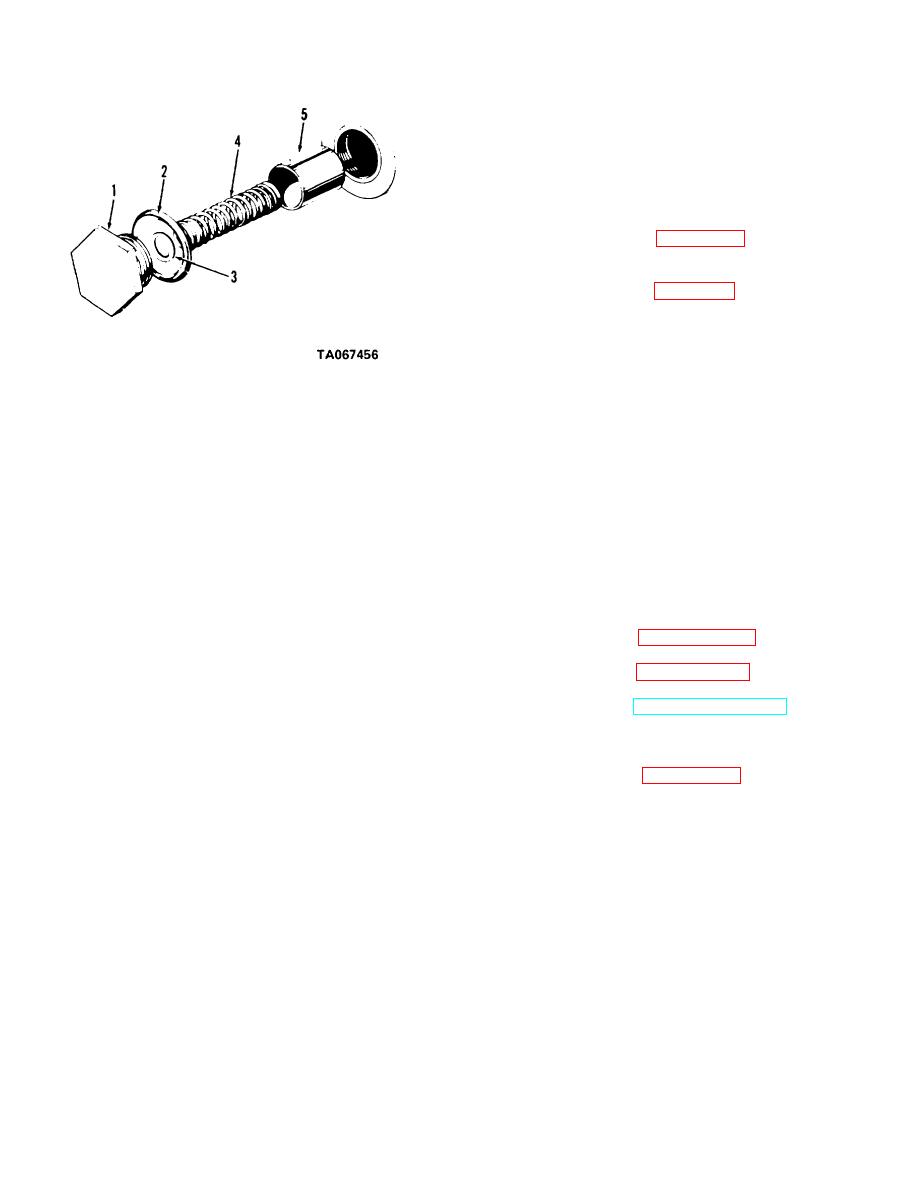
sequence as illustrated in figure 11-16.
b. Adjustment. Adjustment of the oil pressure
relief valve is accomplished by the removal and
installation of washers (3, fig. 11-16) behind spring (4).
(1) With engine at operating temperature, the
recommended pressure at idle speed is 5 to 10 psi (0.35
to 0.70 kg/cm2).
(2) With engine at operating temperature the
recommended pressure at full throttle is 30 to 40 psi (2.1
1 Plug
3 Washer
to 2.8 kg/cm2).
2 Gasket
4 Spring
(3) To increase pressure, add washers (3).
5 Valve
Add washers, one at a time, and check pressure. If after
Figure 11-16. Oil pressure relief valve, disassembly and
installing four washers, pressure is still low, replace
reassembly.
spring (4).
(4) To decrease pressure, remove washers.
11-14. Oil Pressure Relief Valve, Cleaning,
Remove washers, one at a time, and check pressure. If
Inspection and Repair
all washers are removed and pressure is still high,
a. Clean all metal parts in cleaning compound,
replace spring.
solvent (Fed. Spec. P-D-680) and dry thoroughly.
b. Inspect valve for dents, wear and damage.
Section III. PISTONS AND CONNECTING RODS
(1) Refer to paragraph 2-22 and remove the
11-16. Description
engine from the truck.
a. The connecting rods are precision ground and
(2) Refer to paragraph 11-7 and remove the
rifle drilled. They receive the thin-wall precision type
oil pan.
bearing shells to mount to the crankshaft.
(3) Refer to TM 10-3930-630-12 and remove
b. The aluminum pistons have four rings, two
the cylinder head.
compression rings, one scraper ring and one three piece
(4) Use a ridge cutting tool and remove ridge
oil control ring.
at top of piston bores.
(5) Refer to figure 11-17 and remove rod
11-17. Piston and Connecting Rods, Removal and
bearing cap nuts and connecting rod bearing caps and
Disassembly
bearing shells.
a. Removal.
(6) Slide piston and connecting rod up out
the top of the engine crank case.
11-12
|
|
Privacy Statement - Press Release - Copyright Information. - Contact Us |