 |
|||
|
|
|||
|
Page Title:
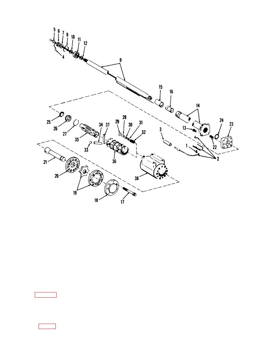
Figure 8-3. Steering gear valve, disassembly and reassembly. |
|
||
| ||||||||||
|
|
 TM 10-3930-630-34
1
Screw
10
Retaining ring
19
Rotor
28
Plug
37
Spring
2
Brush assembly
11
Bearing
20
End plate
29
Packing
38
Housing
3
Connector
12
Retaining ring
21
Drive shaft
30
Seat
4
Wire
13
Screw
22
Screw
31
Ball
6
Ferrule
14
steering column
23
Plate
32
Spring
6
Contact spring
15
Contact ring
24
Oil seal
33
Disk
7
Contact washer
16
Insulator
25
Seal
34
Pin
8
Retaining ring
17
Screw
26
Bushing
35
Control spool
9
Shaft
18
End cap
27
Packing
36
Control sleeve
Figure 8-3. Steering gear valve, disassembly and reassembly.
(4) Control spool rotation. Remove the control
(c) Hold spool assembly down against wooden
assembly from vise and check for free rotation of control
block and lift off mounting plate (23).
spool (35) and sleeve (36). Install assembly in vise as
(d) Inspect mating surfaces of plate and
shown in figure 8-4 and rotate shaft. Shaft should rotate
control for leakage paths and wear. Remove and
freely.
discard oil seal (24) and shaft seal (25) from mounting
(a) Place a wooden block across vise throat to
plate (23).
support spool parts.
(b) Clamp the control assembly across port
face with control end up and remove mounting plate
screws (22, fig. 8-3).
8-5
|
|
Privacy Statement - Press Release - Copyright Information. - Contact Us |