 |
|||
|
|
|||
|
|
|||
| ||||||||||
|
|
 TM 10-3930-630-34
TA067399
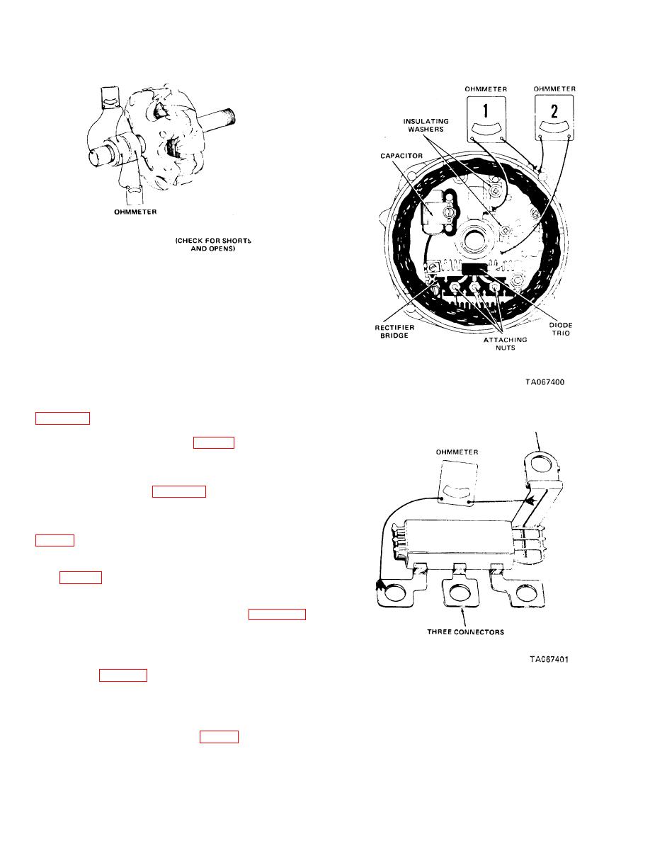
Figure 4-2. Checking rotor.
(3) If coil or slip rings are not open, check
ohmmeter reading. Resistance should be approximately
3 ohms. If reading is low, coil is shorted. Replace rotor
(15) and regulator (17).
(4) Connect ohmmeter leads to one slip ring
and to rotor shaft. If reading is low, rotor coil is
grounded. Replace rotor (15).
c. Drive End Frame Test.
(1) Connect ohmmeter leads using
smallest range scale, as shown (ohmmeter No. 1) on
Figure 4-3. Checking drive end frame.
are the same, check for grounded brush lead clip to end
frame. Check insulating washers (fig. 4-3) and insulating
sleeve for damage. Replace insulating washers or
sleeve on the brush lead, if necessary.
(2) Connect ohmmeter leads as shown
for ohmmeter No. 2 on figure 4-3. Reverse connections.
If both readings are the same again check insulating
sleeve and replace if necessary. If insulation is correct
and both readings are the same, replace regulator (17,
d. Diode Test.
(1) Disconnect diode and remove nuts
(20, fig. 4-1) and remove diode (23) from end frame
(11).
(2) Use the lowest range on the
ohmmeter and connect leads as shown in figure 4-4.
Observe the reading. Reverse connections and again
check reading. If both readings are the same, replace
the diode.
(3) Repeat the test between the single
connector (fig. 4-4) and each of the other two
Figure 4-4. Diode test.
connectors. If readings are the same, replace the diode.
(4) Connect the ohmmeter between each
pair of the three connectors. If any reading is zero,
replace the diode.
(5) Install diode (23, fig. 4-1) in frame and
secure with nuts (20). Collect diode to brushes.
4-3
|
|
Privacy Statement - Press Release - Copyright Information. - Contact Us |