 |
|||
|
|
|||
|
|
|||
| ||||||||||
|
|
 TM 10-3930-630-34
TA067381
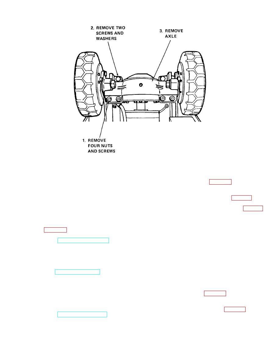
Figure 2-9. Front drive axle, removal and installation
b. Check axle assembly for damage. Check all
adjusting screw.
mounting hardware for defects.
d. Support steering axle with a suitable jack or
blocking. Remove two mounting screws (fig. 2-10), lock
2-30. Front Drive Axle Installation
washers and nuts securing axle housing to frame.
a. Raise truck using a suitable hoist with a
capacity of at least 6,000 pounds. Roll drive axle into
with attached housing from beneath truck.
position under truck. Align mounting pad dowel pins with
correct mounting holes.
2-32. Rear Steering Axle Cleaning and Inspection
b. Carefully lower truck into position on drive
axle. Refer to figure 2-9 and secure axle with screws,
a. Clean the steering axle assembly with
nuts and washers. Remove hoist and chain.
c. Refer to TM 10-3930-630-12 and install
cleaning solvent (Fed. Spec. P-D-680). Dry thoroughly
with compressed air.
parking brake and drive shaft.
b. Check steering axle assembly and all
d. Connect brake hydraulic lines to wheels and
mounting hardware for damage.
to tee at top of axle. Refer to TM 10-39-30-630-12 and
install lift cylinder hydraulic return line, clamps and
wires.
2-33. Rear Steering Axle Installation
e. Refer to TM 10-3930-630-12 and install mast
assembly on lift truck.
a. Lift rear of truck sufficiently and install
steering axle into position. Jack axle up into place on
2-31. Rear Steering Axle Removal
truck. Slide ends of axle into self-aligning bearings in
axle housing and frame (fig. 2-10) and secure axle
housing to truck with two mounting screws, lock washers
a. Attach a hoist with a capacity of at least 6,000
and nuts. Do not tighten completely.
pounds to the truck and lift rear of truck high enough to
gain access to the steering axle.
b. Refer to TM 10-3930-630-12 and remove
spacer to a torque of 10 to 15 foot pounds (1.35 to
floor and toe plates, rear wheels, steering cylinder and
drag
links.
2-16
|
|
Privacy Statement - Press Release - Copyright Information. - Contact Us |