 |
|||
|
|
|||
|
Page Title:
Section IV. REMOVAL AND INSTALLATION OF MAJOR COMPONENTS AND ASSEMBLIES |
|
||
| ||||||||||
|
|
 TM 10-3930-630-34
Section IV. REMOVAL AND INSTALLATION OF MAJOR
COMPONENTS AND ASSEMBIES
eyes. Securely block truck in a raised position.
2-11. General
b. Refer to TM 10-3930-630-12 and drain the
hydraulic reservoir. Plug all hoses and tubes to avoid
a. The major components of the fork lift truck
dirt from entering the hydraulic system.
consist of the control valve, hydraulic pump, steering
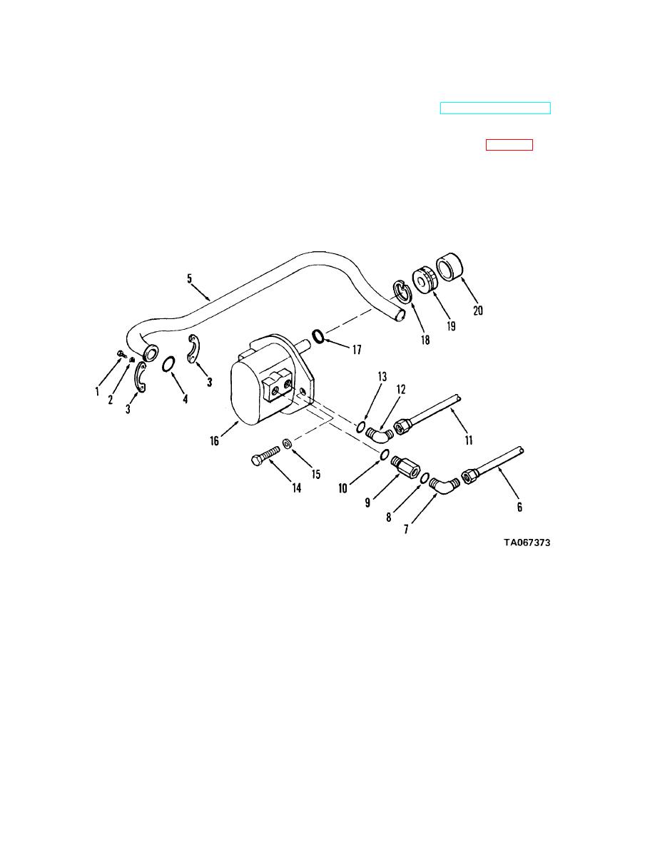
c. Remove screws (1, fig. 2-1) and lock washers
gear valve, engine assembly, service brakes, front drive
(2) and disconnect suction tube (5) from hydraulic pump.
axle,
rear steering axle and the transmission.
Remove split flanges (3) and packing (4). Plug
b.. The paragraphs in this section are for the
tube and pump to prevent entrance of foreign material.
removal and installation of the above components.
d. Disconnect steering hose (6) from elbow (7)
and remove elbow, check valve (9) and packings (8 and
2-12. Hydraulic Pump, Removal
10) from pump. Plug steering hose and pump opening.
a.
Raise up the rear of the truck with a hoist of at
least 6,000 pound capacity attached to the lifting
TA067373
1 Screw
6 Steering hose
11 Outlet hose
16 Hydraulic pump
2 Lock washer
7 Elbow
12 Elbow
17 Packing
3 Split flange
8 Packing
13 Packing
18 Retaining ring
4 Packing
9 Check valve
14 Screw
19 Hydraulic pump gear
5 Suction tube
10 Packing
15 Lock washer
20 Sleeve
Figure 2-1. Hydraulic pump, removal and installation.
e. Disconnect large outlet hose (11) from elbow
2-13. Hydraulic Pump, Cleaning and Inspection
(12) and remove elbow and packing (13) from pump.
Plug outlet hose and pump opening.
a. Clean hydraulic pump in cleaning solvent,
f. Remove screws (14) and lock washers (15)
(Fed. Spec. P-D-680). Dry thoroughly with compressed
and carefully remove hydraulic pump (16) from engine
air.
gear cover. Remove packing (17).
b. Inspect pump for cracks, breaks, or other
g. Remove retaining ring (18) and pump gear
damage.
(19) from sleeve.
2-5
|
|
Privacy Statement - Press Release - Copyright Information. - Contact Us |
