 |
|||
|
|
|||
|
Page Title:
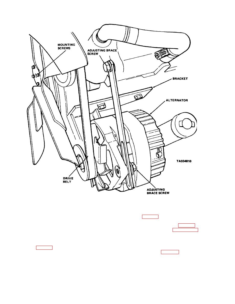
Figure 4-35. Alternator, installed view. |
|
||
| ||||||||||
|
|
 TM 10-3930-630-12
Figure 4-35. Alternator, installed view.
e. Removal.
CAUTION
(1) Open left side panel to gain access to
alternator (fig. 4-35).
(2) Remove nut and lockwasher and
Tab for screwdriver in test hole is within
disconnect wire from alternator (fig. 4-35).
3/4 inch of casting surface. Do not
(3) Refer to figure 4-35 and loosen
force screwdriver deeper than one inch
alternator adjusting brace screw. Loosen nuts on long
into hole.
screw attaching bottom of alternator to alternator
(6) If ammeter reads less than 27 amps,
bracket.
ground the field winding by inserting a screwdriver into
(4) Push alternator towards engine and
the test hole (fig. 4-36).
disengage drive belt (fig. 4-35) from alternator pulley,
(7) Operate engine at moderate speed
fan
and adjust load rheostat to obtain maximum current
output. If output exceeds 27 amps, replace alternator.
4-45
|
|
Privacy Statement - Press Release - Copyright Information. - Contact Us |
