 |
|||
|
|
|||
|
Page Title:
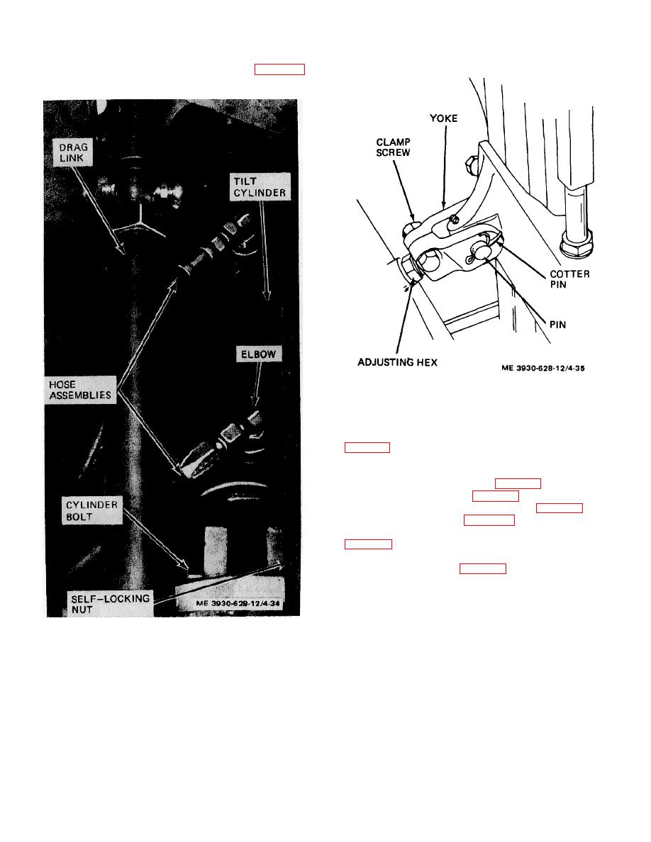
Figure 4-34. Tilt cylinder, installed view. |
|
||
| ||||||||||
|
|
 TM10-3930-628-12
Remove cotter pins and remove yoke pin (fig.
from yoke and mast.
ME 3930-628-12/4-35
Figure 4-35. Tilt cylinder yoke, installed view.
(5) Remove cylinder bolt and self-locking nut
(6) Remove cylinder from truck.
c. Installation. Install tilt cylinder in truck as follows:
(1) Install tilt cylinder (fig. 4-34) in position on
truck. Install cylinder bolt (fig. 4-34) through frame and
cylinder and secure with self-locking nut (fig. 4-34).
(2) Install pin (fig. 4-35) through mast and
yoke at front of cylinder. Secure pin with two cotter pins
(3) Remove plugs from hoses and cylinder and
connect hose assemblies (fig. 4-34) to tilt cylinder.
d. Tilt Adjustment. Normal tilt of the mast is 30
forward and 100 backward. Operate tilt cylinders and
check tilt angle with a protractor as shown in
Figure 4-34. Tilt cylinder, installed view.
4-34
|
|
Privacy Statement - Press Release - Copyright Information. - Contact Us |
