 |
|||
|
|
|||
|
|
|||
| ||||||||||
|
|
 TM 10-3930-628-12
c. Battery Receptacle and Cables.
and are mounted in fuse holders. Two are mounted with
(1) Removal. Disconnect receptacle (fig. 4-
the power switch, four are mounted in the contactor box.
2).Unsolder cables from receptacle connector.
b. Removal and Installation. Remove fuses
(2) Installation. Solder cables to receptacle.
from holders and install identical fuses in their place.
Connect removable receptacle to lower receptacle and
Loosen screws to remove main fuse from contactor box.
secure with lever.
4-28.
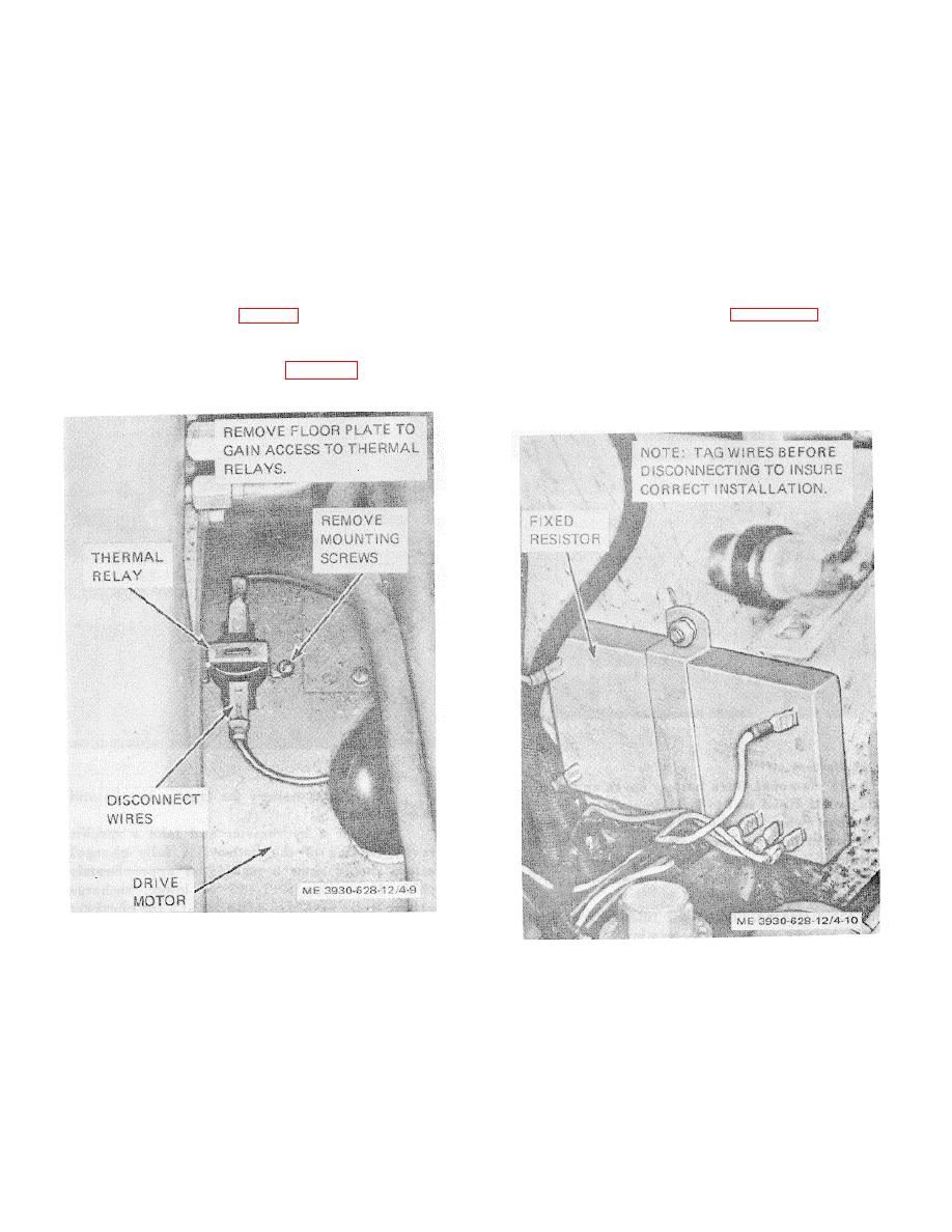
Fixed Resistor.
4-26.
Thermal Relay.
a. General. The fixed resistor is mounted on
a. General. Thermal relays are installed in the
the frame forward of the master cylinder. Remove the
circuits to prevent overheating of the motors and the
floor and toe plates to gain access to the resistor. Report
hydraulic oil. The switches are normally closed and open
any defects to direct and general support maintenance
when the heat reaches a point where it could injure the
personnel.
component. Two switches (fig. 4-9) are mounted on the
b. Inspection. Refer to figure 4-10 and inspect
hydraulic reservoir and one each on the drive and pump
resistor as follows:
motors.
(1) Inspect fixed resistor for secure mounting.
b.
Remotval. Refer to figure 4-9 and remove
(2) Check resistor for cracks and other
the thermal relays.
damage.
(3) Check wires for damage and secure
connections.
Figure 4-9. Thermal relay, installed view.
c. Installation. Refer to 4-9 and install the
Figure 4-10. Fixed resistor, installed view.
thermal relays.
4-27. Fuses.
a. General. The fuses are of the cartridge type
4-12
|
|
Privacy Statement - Press Release - Copyright Information. - Contact Us |