 |
|||
|
|
|||
|
|
|||
| ||||||||||
|
|
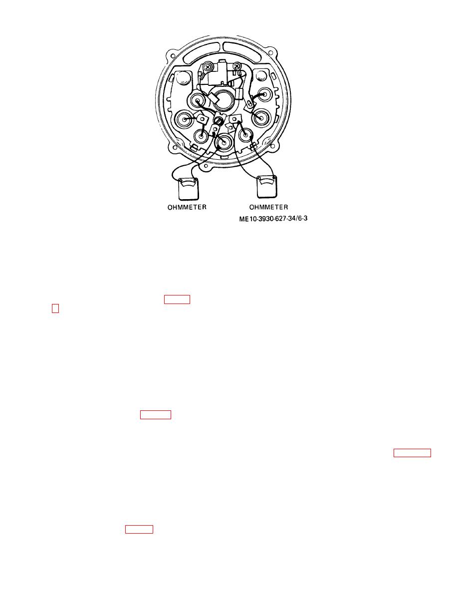
 Figure 6-3. Diode Check.
and bearing retainer (25). Secure bearing retainer with
Caution: Do not attempt to polish
three screws (26).
slip rings without rotating rotor as
b. If bearing (4) has exhausted its lubricant, replace
they must be polished evenly.
bearing. Press it out of frame with tube or collar that
Cleaning by hand may result in flat
just fits inside frame bore. Press from outside of
spots which will cause brush noise.
housing toward inside. Place flat plate over new bearing
Inspect slip rings on rotor (7, fig. 6-
and press it in from outside of frame toward inside until
it is just flush with outside of frame. Support inside of
polishing cloth, 400 grain or finer.
frame with hollow cylinder to avoid breakage. Use
Spin rotor in lathe or equivalent, and
extreme care to avoid misalignment or placing undue
hold polishing cloth against slip
stress on bearing. Saturate felt seal of retainer (5) with
rings until they are clean.
OE 20 and assemble it in frame.
c. Check brushes to see if they have come in contact
o. Check slip rings for roughness or out-of-round. If
with lubricant. If so, wipe brushes with a soft, dry cloth.
they are rough or out-of-round, they should be trued on
Check brush springs (19) for damage or corrosion. If
a lathe to 0.002 inch tolerance. Remove only enough
there is any doubt as to condition of springs, replace
material to make rings smooth and round. Finish by
them. If new brushes are to be installed, remove brush
polishing with a cloth, 400 grain or finer. Blow all dust
holder assembly from frame by removing brush holder
from rotor and rings after polishing.
screws (18). Remove brushes and springs from brush
holders. Install new brush springs and brushes and
bearing retainer (25) to drive frame (10); remove inside
insert a straight wire or pin into hole at bottom of brush
collar (28) and gasket (27). Press bearing (20) from
holder to retain brushes. Position assembled brush
drive frame; remove grease slinger (30).
holder on frame and secure with two screws. Make sure
Caution: Do not fill bearing more
parts are in correct relationship as shown in figure 6-1.
than one-quarter full or it may
Allow straight wire or pin to protrude through hole in end
overheat.
Do not use any other
frame.
lubricant than lubricant specified. If
bearing is in satisfactory condition,
procedure. Make sure to remove tape from rotor shaft
fill it one-quarter full with lubricant.
and frame bearing. When holding rotor in a vise to
6-3. Alternator Assembly
install rotor in frame, tighten vise only tight enough to
a. Install grease slinger and press bearing in drive
permit torquing nut (32) to 50 to 60 foot-pounds.
frame, using a tube or collar that just fits over outer
Withdraw wire used when assembling
race. Install new gasket (27, fig. 6-1), inside collar (28),
6-4
|
|
Privacy Statement - Press Release - Copyright Information. - Contact Us |