 |
|||
|
|
|||
|
Page Title:
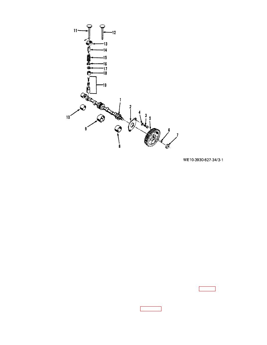
Figure 3-1. Values and camshaft, exploded view. |
|
||
| ||||||||||
|
|
 1.
Camshaft
11. Intake valve
2.
Thrust plate
12. Exhaust valve
3.
Screw
13. Exhaust seat insert
4.
Washer
14. Guide
5.
Camshaft gear
15. Spring
6.
Woodruff key
16. Spring retainer
7.
Nut
17. Spring retainer lock
8.
Front camshaft bushing
18. Roto cap assembly
9.
Center Camshaft bushing
19. Tappet assembly
10.
Rear camshaft bushing
Figure 3-1. Values and camshaft, exploded view.
b. Cleaning and Inspection.
(5) Inspect exhaust valve seat inserts (13).
Replace inserts if loose or scored, or if they cannot be
(1) Clean carbon from valves with scraper or wire
properly faced (step d. below).
brush and wash in solvent. Clean valve guides (14) and
ports with wire brush.
(6) Inspect tappets for worn threads, scores,
(2) Replace valves if the faces are badly cracked,
cracks and wear or pitting of the face.
scored, warped or burned. Reface valves and seats if
(7) Examine adjusting screws for worn or
slight evidence of these conditions exists. Intake valve
damaged threads. Adjusting screws must be tight in
seat angle is 30and exhaust valve seat angle is 45
tappets when turned with a wrench. Replace them if
they are worn or damaged.
(3) Test valve springs for loss of strength. A
c. Valve Guide Replacement.
reusable valve spring will require at least 86 pounds
(1) Using a drift or piloted driver, drive old valve
force to compress it to 1 27/64 inch length. Inspect
guide from the cylinder block (fig. 3-2).
springs for cracks or breaks.
(2) Using a piloted driver, drive new guide into
(4) Inspect valve stems for good condition and
the cylinder block. Drive guide until its top is 1 15/32
proper clearance in valve guides. Replace valve if stem
inch from the top of the block, as measured according to
is bent over 0.002 inch. If inside diameter of any guide
is worn, to more than 0.0015 inch oversize, replace
valve guide (step c. below).
3-2
|
|
Privacy Statement - Press Release - Copyright Information. - Contact Us |