 |
|||
|
|
|||
|
Page Title:
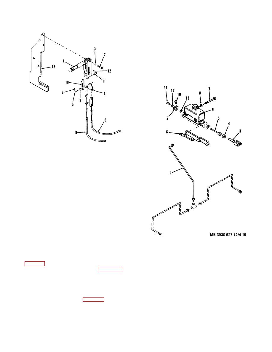
Figure 4-18. Hand brake lever and cable replacement. |
|
||
| ||||||||||
|
|
 TM 10-3930-627-12
c. Disconnect stop light wires at stop light switch
(10).
d. Loosen jam nut (4) and unscrew push rod (5)
from clevis (3).
e. Remove screws (7) and washers (8) and take
master cylinder (9) from bracket (6).
f.
Remove switch (10), connector bolt (11)
and washers (12 and 13) for reuse, as they may not be
included with a rebuilt master cylinder.
g. Install by reversing steps a to e above. Fill
reservoir with specified fluid and bleed brakes
ME-3930-627-1 2/4-18
1. Hand brake lever
2. Cap screw
3. Lock washer
4. Equalizer plate
5. Pin
6. Cotter pin
7. Flat washers
8. Cable assembly
9. Cable assembly
10. Link
11. Pin
12. Cotter pin
13. Mounting bracket
Figure 4-18. Hand brake lever and cable replacement.
b. Lever and Cable Replacement.
(1) Remove cap screws (2) and lock
washers (3) to free lever assembly from bracket (13) on
1. Brake tube
truck frame.
2. Tube fitting
(2) Remove pins holding cables (8 and 9)
3. Clevis
to equalizer plate (4) and take lever from truck. To
4. Jam nut
remove cables disconnect them at the axle and lever
5. Push rod
(13, fig. 4-23) and take them from the truck. Reverse
6. Mounting bracket
this procedure to install cables. Refer to figure 4-18 to
7. Screw
salvage any usable parts of the assembly.
8. Washer
(3) Install lever by reversing steps (1) and
9. Master cylinder
(2) above.
10. Switch
4-40. Master Cylinder Replacement
11. Connector bolt
a. Remove truck floor plate.
12. Washer
b. Disconnect tube ( 1, fig. 4-19) from tube
13. Washer
fitting (2).
Figure 4-19. Brake master cylinder replacement.
4-24
|
|
Privacy Statement - Press Release - Copyright Information. - Contact Us |