 |
|||
|
|
|||
|
Page Title:
Cleaning. Inspection and Repair. |
|
||
| ||||||||||
|
|
 (5) Remove the snap rings (9, 10 and 11),
bearing (12) and reverse gear (13).
(6) Remove the capscrews (14), lockwashers
(15). retainer (16) and gasket (17). Note the
position of the pin (18). Remove the pin and idler
shaft (19). Remove the idler gear (20) and the
bearings (21).
(7) Remove the seal (22), capscrews (23),
lockwashers (24). retainer (25) and gasket (26).
Remove the output shaft (27). tapping with a soft
hammer if necessary. Remove the bearings (28),
plug (29) and output gear (30).
(8) Remove the dipstick (31), plugs (32, 33
and 34), spring (35) and filter screen (36). Scrape
the gasket (37) from the face of the housing (38).
c. Cleaning. Inspection and Repair.
(1) Clean ail components in suitable solvent.
Dry with compressed air.
(2) Follow general inspection procedures (para
(3) Inspect gears for broken, cracked, worn or
chipped teeth. Replace damaged or worn gear.
(4) Inspect the output flange for cracks,
breaks and other damage. Check the spline for
ME 3930-6247-34/4-6
damage and wear. Repair or replace the flange if
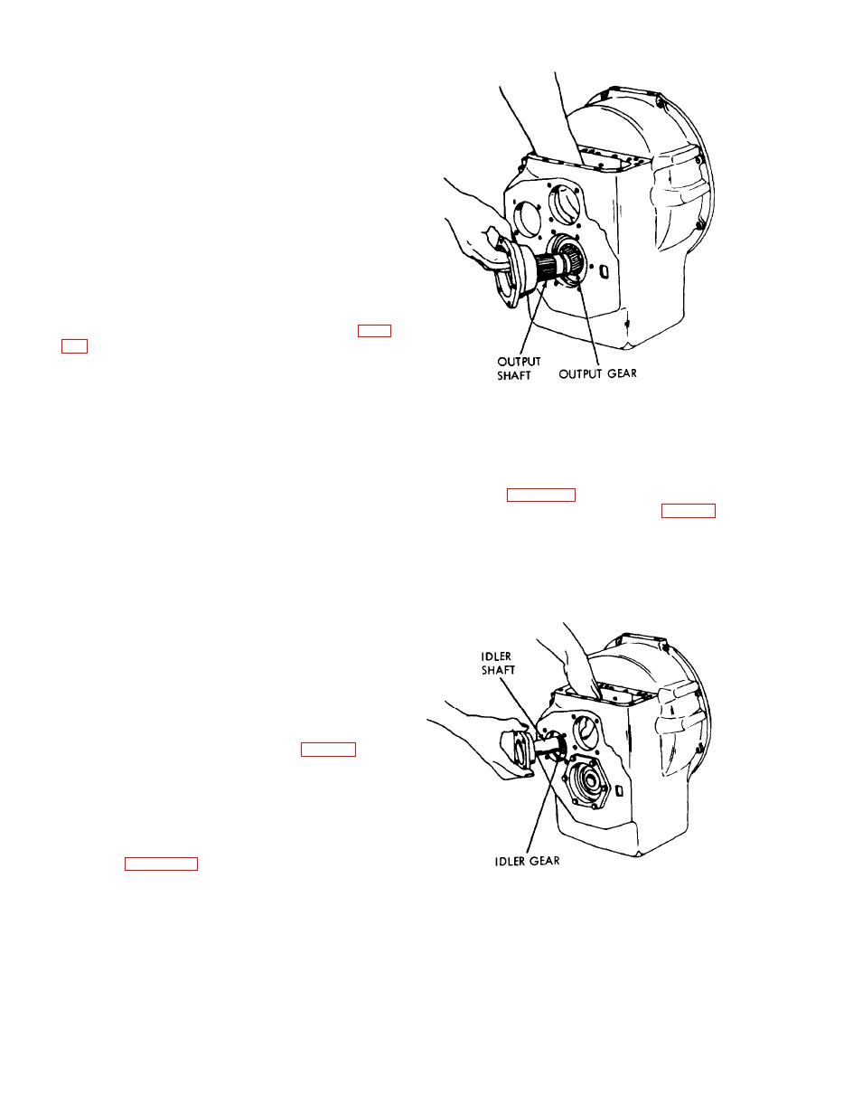
Figure 4-6. Installing output gear and shaft.
damaged.
(5) Inspect the forward, reverse and idler
shafts for cracks, breaks, worn splines, and other
(4) Install the idler shaft (19, fig.4-5) and gear
damage. Repair or replace if damaged.
(20). Refer to figure 4-7. Ensure that the machined
(6) Inspect the idler shaft for cracks, breaks
reliefs on the idler shaft retainer (16, fig. 4-5) are
and other damage. Replace if damaged.
positioned down so that oil in the retainer can drain
(7) Inspect bearings for burrs and rough spots.
into the transmission case.
Light scratching will not impair operation. Smooth
minor roughness with a soft hone or crocus cloth.
Replace abrasive bearings.
(8) Inspect the filter screen and spring for
corrosion and damage. Blow out clogged passages
with compressed air. Replace if necessary.
(9) Inspect the housing and retainers for chips,
cracks and other damage. Repair by welding if
feasible or replace as required.
d. Reassembly. Reassemble the transmission in
the reverse order of disassembly. Observe the
following:
(1) Ensure that the spring (35, fig. 4-5) is in
place when installing the filter screen (36).
them with transmission lubricant and make sure
they rotate.
(3) Install the output shaft (27) so that the
internally splined end extends outside the gear case.
Refer to figure 4-6.
MF 3930-624-34/4-7
Figure 4-7. Installing idler gear and shaft.
4-6
|
|
Privacy Statement - Press Release - Copyright Information. - Contact Us |