 |
|||
|
|
|||
|
|
|||
| ||||||||||
|
|
 thickness of the compressed lead or plastic strip.
c. Reassembly and Installation.
The clearance between the shells and the journals
(1) Proceed as follows if the old main bearing
should be 0.0013 to 0.0040 inch at all main
caps are to be installed:
bearings. Install new bearing shells if this clearance
(a) Install the upper halves of the main
exceeds 0.007 inch.
bearing shells (9, fig 3-18) in the main bearing seats
(c) Measure the inside diameter of the
of the cylinder block. Make sure that the bearing
bearing cap installed and tightened to a torque of
shell tangs are properly located in corresponding
110 to 120 ft lbs. The specified inside diameter of
slots in the bearing seats of the cylinder block. The
new bearings is 2 . 5 0 0 7 - 2 . 5 0 2 4 i n c h e s . Any
flanged bearing shell is always installed at the
d e v i a t i o n b e l o w 2.5007 inches indicates the
center main bearing location.
amount of bearing wear.
(b) Lubricate all crankshaft main bearing
(d) Measure the diameter of the crankshaft
journals. Lower the crankshaft (10) into the
journal at corresponding bearing locations and
cylinder block with the flywheel flange end of the
subtract this dimension from the inside diameter
shaft toward the rear.
(c) Place the lower halves of the main
measurement of the bearing. The difference be-
bearing shells (9) in the main bearing caps (8).
tween these two measurements is the crankshaft to
inserting tangs of the shells into the slots in the
bearing clearance. The bearing shells do not form a
caps. The bearing caps are numbered one through
true circle when they are not installed. When
six, indicating their respective positions. Insert the
measuring for inside diameter, install the bearings
flanged shell in the center main bearing cap.
in the cylinder block and tighten the capscrews to
(d) Install the bearing caps (8) with the
110 to 120 ft Ibs. The two halves of the shell have a
numbers corresponding to the numbers stamped on
squeeze fit in the seat and bearing cap, and must be
the lower left side of the cylinder block, and secure
tight when the cap is drawn down.
with lockwashers (7) and capscrews (6).
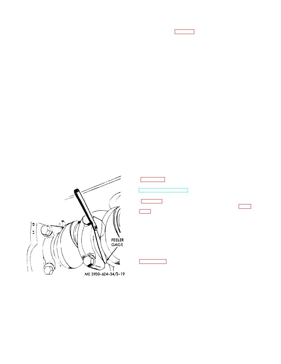
(e) Check the end play of the crankshaft,
Caution: Do not overtighten the main
which is taken up by the thrust flanges of the center
hearing capscrews. Bearing caps may distort
main bearing shell. Refer to figure 3-22. The
causing bearings to be drawn tight against the
specified end play is 0.003-0.009 inch and should
crankshaft resulting in prermature failure.
not exceed 0.015 inch. If worn beyond the specified
limit, the bearing shell should be replaced.
to 120 ft Ibs.
(f) Install the flywheel and flywheel housing
(g) Install the starter motor as instructed in
TM 10-3930-624-12.
(h) Install the transmission to the engine
(j) Service the engine with lubricating oil
and coolant.
(2) Proceed as follows if new main bearing
caps are to be installed:
(a) Loosely install two 1/4 x 2 inch long
temporary locating dowels in the two inch dowel
holes in the cylinder block. Place the dowels where
the replacement cap is to be installed. Refer to
Figure 3-19. Checking crankshaft end play.
3-22
|
|
Privacy Statement - Press Release - Copyright Information. - Contact Us |