 |
|||
|
|
|||
|
Page Title:
The specified clearance is 0.003-0.008 inch. |
|
||
| ||||||||||
|
|
 crankshaft. Make sure the gear timing mark is
(3) Remove the governor. Refer to paragraph
aligned with the camshaft gear timing mark. It may
be necessary to tap the gear with a wood block and
(4) Remove the front support capscrews and
a hammer to seat it against the crankshaft shoulder.
raise the front end of the engine approximately 2
(c) Allow the gear to cool gradually; do not
inches. Block the engine in this position.
immerse in water or oil.
(5) Remove the capscrews, lockwashers, stud
(3) Install the fuel pump. Refer to TM 10-
nut, and lockwasher attaching the timing gear
3930-624-12. Install the governor assembly. Refer
cover to the front plate and oil pan.
(6) Tap the cover lightly to remove the cover.
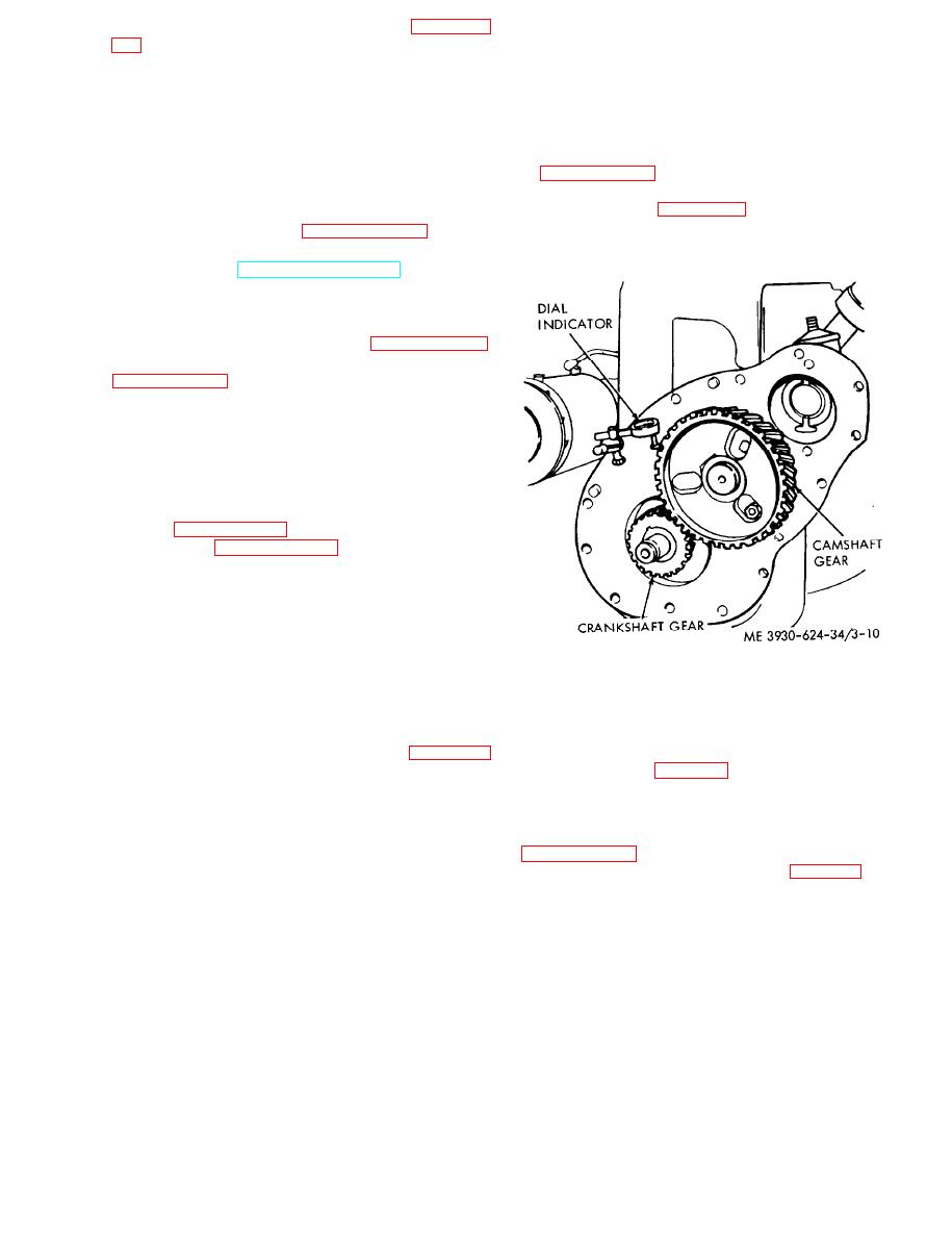
(4) Check the backlash of the gears with a dial
Do not attempt to pry the cover off.
indicator. Refer to figure 3-10. One or more of the
(7) Remove the retaining clip and remove the
mating gears should be replaced if the backlash
camshaft gear. Refer to paragraph 3-1.5.
exceeds 0.008 inch.
(8) Remove the fuel pump from the side of the
engine. Refer to TM 10-3930-624-12. Place a bar
through the opening against the side of the cam to
hold the camshaft in a forward positinn.
(9) Use a gear puller to remove the crankshaft
gear from the crankshaft. Refer to paragraph 3-17.
(10) Remove the governor drive gear. Refer to
b. Cleaning and Inspection.
(1) Clean the timing gear cover. timing gears,
and mounting hardware with a cleaning solvent.
(2) Inspect the timing gear cover for dents,
cracks, corrosion.
(3) Inspect the gears for nicked, scored, or
broken teeth. Replace any worn or damaged parts.
Refer to paragraph 3-15 for camshaft gear in-
spection and paragraph 3-17 for crankshaft gear
inspection.
c. Installation.
(1) Use the following procedure to install the
camshaft gear:
(a) Line up the camshaft gear on the key.
Drive the gear onto the camshaft using a block of
Figure 3-10. Checking gear backlash.
hardwood and a hammer. Drive the gear on far
enough so the thrust plate rests against the cam-
(5) Install a new gasket and install the timing
shaft journal.
gear cover.
(b) Check the clearance between the thrust
(6) Install the crankshaft pulley and
plate and the bearing journal. Refer to paragraph
hydraulic pump (para 5-5).
3-15. The specified clearance is 0.003-0.008 inch.
(c) Install the retaining clip.
3-14. Flywheel Assembly
(d) Remove the bar which was used to hold
a. Removal and Disassembly.
the camshaft in position.
(1) Remove the transmission. R e f e r t o
(2) Use the following procedure to install the
crankshaft gear:
(2) Remove two capscrews (1, fig. 3-11) and
(a) Install the key in p o s i t i o n o n t h e
lockwashers (2) which are horizontally opposite
crankshaft.
and install two guide studs. Attach a sling to the
(b) Heat the crankshaft gear in boiling oil
flywheel (3) and remove the remaining capscrews
for approximately 15 minutes. Pick up the gear
(1). Slide the flywheel off the guide studs.
with a tongs or pliers and slide the gear onto the
3-13
|
|
Privacy Statement - Press Release - Copyright Information. - Contact Us |
