 |
|||
|
|
|||
|
Page Title:
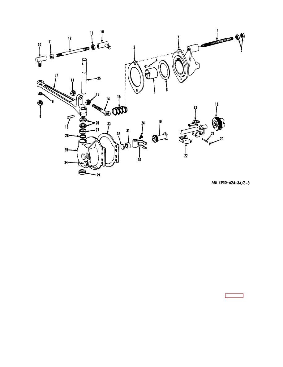
Figure 3-3. Governor, exploded view. |
|
||
| ||||||||||
|
|
 bearing (5) and thrust washer (6) from the adapter
(2) Disassemble the governor body as follows:
housing (7).
2.5.
Rocker shaft
13.
Nut
1.
Control shaft
26.
Oil seal
14.
Eye screw
2.
Nut
27.
Bearing
15.
Spring
3.
Gasket
28.
Snap ring
16.
Pin
4.
Dowel
29.
Bushing
17.
Governor
5.
Bearing
30.
Yoke
18.
Gear
6.
Thrust washer
31.
Bushing
19.
Sleeve and bearing assembly
7.
Adapter housing
32.
Thrust disc
20.
Clip
8.
Nut
33.
Gasket
21.
Pin
9.
W asher
34.
Capscrew
22.
W eight
10.
Joint
35.
Body
23.
Spider and shaft assembly
11.
Nut
24.
Capscrew
12.
Governor control rod
Figure 3-3. Governor, exploded view.
(a) Remove the governor control rod (12),
Remove the rocker shaft and seals and bushings.
eye screw (14) and governor lever (17).
Remove the yoke (30).
(b) Remove the spider and shaft assembly
c. Cleaning, Inspection and Repair.
(23), drive gear (18) and sleeve and bearing
(1) Clean all components with a cleaning
assembly (19) as a unit from the body (35).
solvent and thoroughly dry with compressed air.
(c) Pull the governor drive gear (18) from
(2) Inspect the rocker shaft (25. fig. 3-3) and
the shaft. Remove the sleeve and bearing assembly
bearing (27) for scoring and wear. Replace if the
lever shaft does not rotate freely in the governor
(19) and weights (22).
(d) Remove the capscrews (24) which
body.
(3) Slide the thrust disc (32) and bushing
secure the yoke (30) to the rocker shaft (25).
3-4
|
|
Privacy Statement - Press Release - Copyright Information. - Contact Us |