 |
|||
|
|
|||
|
|
|||
| ||||||||||
|
|
 terminal. Press horn button and note the voltage. If the
4-42. Horn
voltage is between 0 and 10.7 volts, replace the horn.
a. Removal.
(2) If the horn signal is weak and the voltage
(1) Tag and disconnect electrical leads to the
is normal at the horn terminal, check the volume
horn.
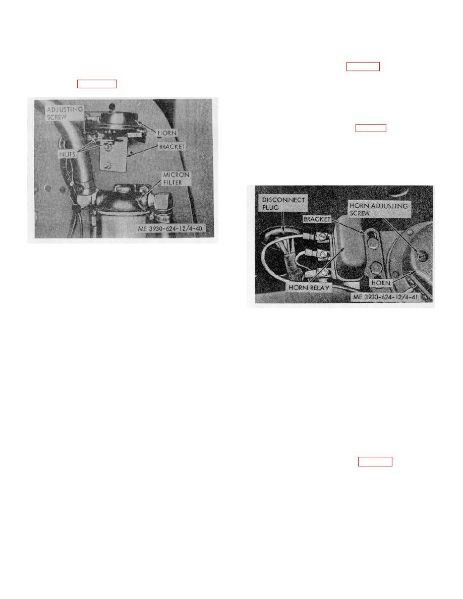
adjusting screw in horn cover (fig. 4-40). Turn the screw
(2) Remove the two nuts and lockwashers
clockwise to increase the volume or counterclockwise to
securing the horn to the mounting bracket. Remove the
decrease the volume.
horn. Refer to figure 4-40.
4-43. Horn Relay
a. Removal. Remove two nuts, washers, and
capscrews securing the horn relay to the bracket. Tag
and disconnect wiring. (Refer to fig. 4-41.)
b. Cleaning and Inspection.
(1) Clean the relay housing with a cloth
dampened with a solvent.
(2) Check the relay assembly for corrosion,
dents, cracks, or other damage. Replace if necessary.
Figure 4-40. Horn mounting and adjusting screw.
b. Cleaning and Inspection.
(1) Clean the horn with a cloth dampened
with a solvent.
(2) Check the horn for cracks, corrosion, and
other damage. Replace the horn if damaged.
c. Installation. Install in the reverse order of
Figure 4-41. Horn relay.
removal.
d. Adjustment.
(1) If the horn produces a weak signal,
c. Installation. To install horn relay, reverse the
connect a voltmeter from the ground to the horn
removal procedure.
Section XII. MAINTENANCE OF THE TRANSMISSION
heat exchanger and back to the transmission.
4-44. General
a. The transmission is mounted between the
engine and the drive axle assembly, immediately below
4-45. Transmission Oil Lines and Filter
the operator's seat. The transmission is connected to
a. Filter Service.
the torque converter on one end, and to the universal
(1) To change the transmission fluid, run the
joint on the other. It is a constant mesh, full reversing,
truck to warm the fluid to operating temperature. Drain
power shift type. The forward and reverse directions are
the fluid by removing the transmission drain plug from
selected by positioning the power shift lever mounted on
the bottom of the transmission (fig. 4-42). Drain fluid
the steering column. The power shift lever is connected
from torque converter by removing the floor plate, and
by a mechanical linkage to the selector valve on the
the inspection cover from the torque converter housing.
transmission.
Remove the drain plug. Rotate the torque converter
b. The transmission fluid is cooled by a heat
180. The fluid in the converter will flow into the
exchanger located in the lower part of the radiator. The
transmission, and will drain from the transmission drain
fluid is pumped from the transmission, through the
plug.
4-37
|
|
Privacy Statement - Press Release - Copyright Information. - Contact Us |