 |
|||
|
|
|||
|
Page Title:
Section XI. MAINTENANCE OF THE ELECTRICAL SYSTEM |
|
||
| ||||||||||
|
|
 (9) Install the hydraulic pump by direct
b. Replacement.
reversal of the removal procedure. Install the rear grille.
(1) Remove the rear grille from the
(10) Install the side panels and the lower seat.
counterweight.
(2) Raise the operator's seat and remove the
side panels.
(3) Remove split flange on the suction tube
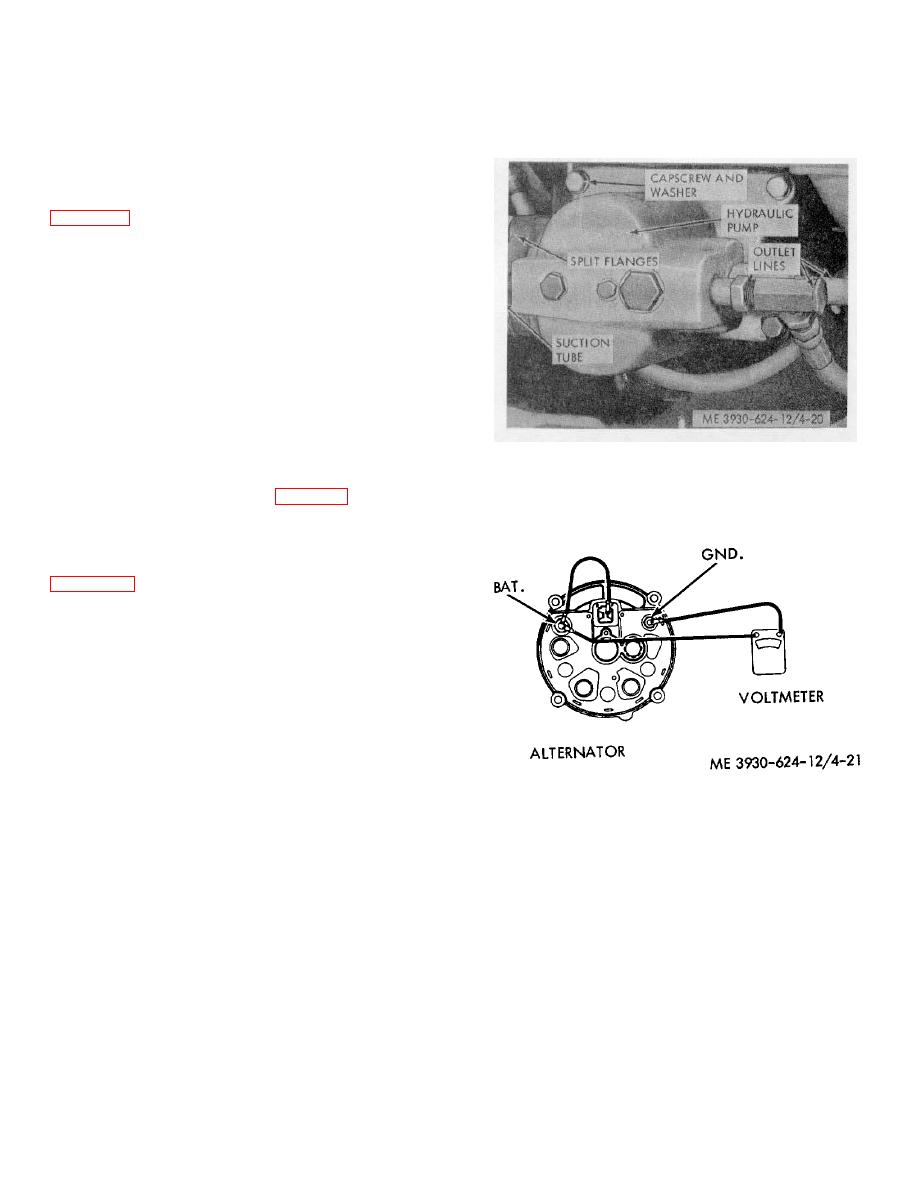
on the hydraulic pump; remove the pump as shown in
(4) Remove the four capscrews and washers
securing the pump to the engine block. Slide the pump
away from the engine block to provide enough
clearance to install the fan belt.
(5) Loosen the alternator to relieve the
tension on the fan belt. Slide the belt from the
crankshaft pulley.
(6) Slide the belt off the alternator pulley,
then off fan pulley and over the fan.
Caution: Care should be not taken. To
bend the radiator fins.
(7) Install a new belt over the fan and around
Figure 4-20. Hydraulic pump removal.
the fan pulley, alternator pulley and crankshaft pulley.
(8) Adjust the fan belt (para 4-31).
Section XI. MAINTENANCE OF THE ELECTRICAL SYSTEM
4-32. General
The electrical wiring diagram for the truck is shown is
distributor, alternator, ignition coil, spark plugs, starter
motor, solenoid, current and voltage regulator, wiring,
and accessories.
Electrical gages and horn are
protected by fuses in the circuit. Fuses are located on
the underside of the instrument panel. The instrument
panel wiring terminates in a multiple male connector.
The engine, accessories, and chassis wiring terminates
in a multiple female connector to provide a quick
disconnect for ease of service.
4-33. Alternator
a. Testing the Alternator.
Figure 4-21. Checking alternator output.
(1) Disconnect the four terminal connector
from the regulator.
b. Removal.
(2) Disconnect the two-terminal connector
Warning: Always disconnect the
from the alternator F and R terminals.
battery cable from the negative
(3) Connect a jumper wire from the BAT
terminal to the F terminal on the alternator.
battery post before making electrical
(4) Connect a voltmeter from the alternator
repairs on the truck.
BAT terminal to the GRD terminal.
(1) Tag the electrical leads to alternator;
(5) Start the engine and turn on the lights.
disconnect the leads.
Run the engine at 1500 RPM or above and note whether
(2) Loosen the fan belt and remove the
voltage exceeds 12.5 volts. If voltage exceeds 12.5 in a
alternator.
few minutes, the alternator output is operating normally.
c. Installation.
Stop the engine, turn off lights and connect wiring.
(1) Install the alternator by reversing the
removal procedure.
4-25
|
|
Privacy Statement - Press Release - Copyright Information. - Contact Us |