 |
|||
|
|
|||
|
|
|||
| ||||||||||
|
|
 (8) Install any other
parts
which
were
(3) Idle fuel adjustment.
removed for carburetor repairs.
(a) Turn the idle adjusting jet (4)
clockwise to obtain a lean mixture or turn
counterclockwise to obtain a rich mixture.
4-20.
Fuel Pump
(b) Adjust the idle screw until the
engine runs smoothly.
a. Testing.
b. Removal.
(1) Disconnect the fuel outlet line at the fuel
(1) Lift the operator's seat, and remove the
pump. Install a 0 to 10 psi pressure gage to the outlet
side panel from the left side of the truck.
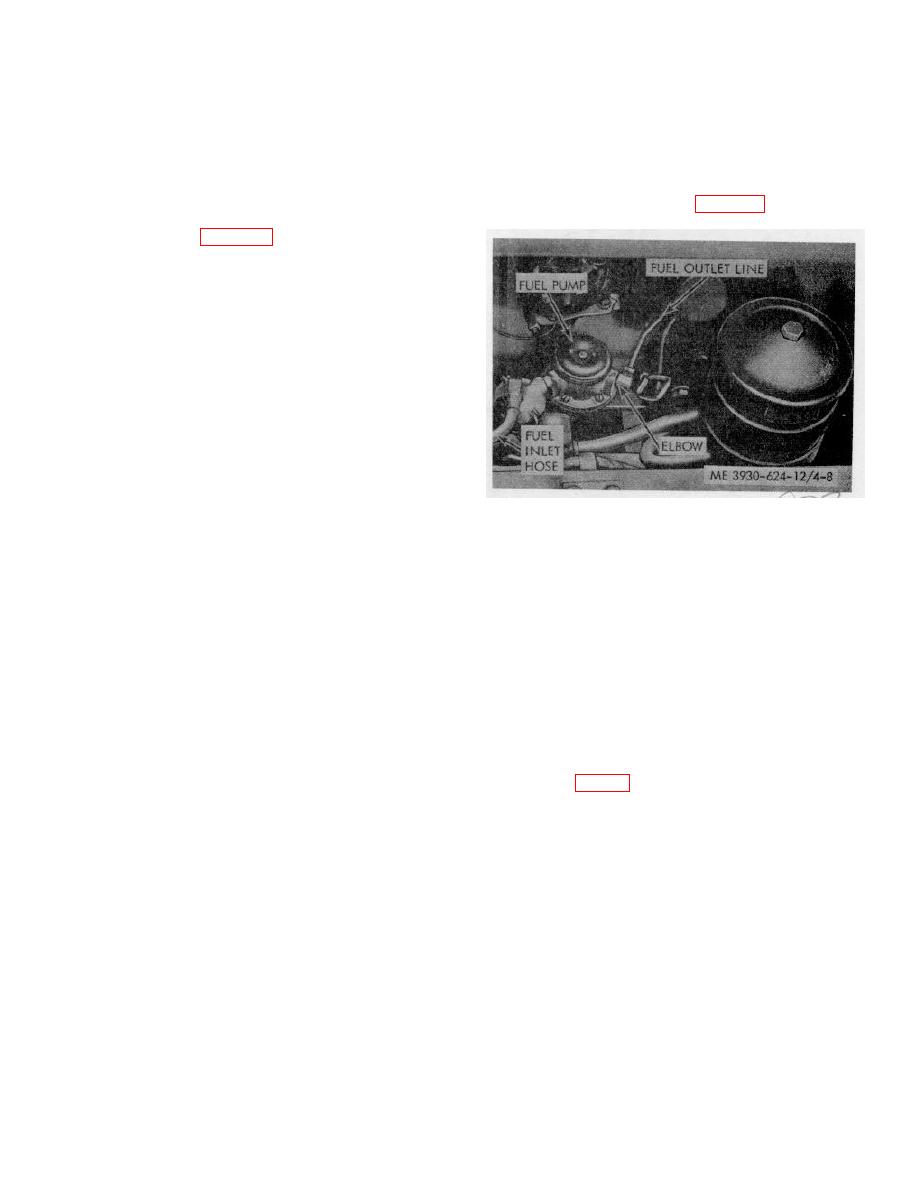
port of the fuel pump. Refer to figure 4-8.
(2) Remove the air cleaner and air cleaner
hose from carburetor (para 4-25).
(3) Disconnect the fuel inlet line (6).
(4) Remove the accelerator rod (1) and
governor control rod (5). Note the position of the throttle
lever and governor lever before removing the control
rods.
Note. Do not change the lengths' of rods.
(5) Disconnect the choke control cable (11).
(6) Remove the two nuts and lockwashers (3)
attaching the carburetor to the intake manifold, and
remove the carburetor.
c. Installation.
(1) Install a new gasket over the studs in the
carburetor mounting flange.
Figure 4-8. Fuel pump.
(2) Install the carburetor on the intake
manifold and secure with two nuts and lockwashers (3).
(2) Run the engine at 1800 rpm on the fuel
(3) Position the choke control cable (11) in
remaining in the carburetor.
the choke bracket (10) and install the choke in the
(3) Note the pressure on the pressure gage.
swivel connection (9).
The pressure should be between 21/2 and 33/4 psi.
(4) Install the governor control rod (5) on the
(4) If the pressure does not fall within these
governor throttle lever (7).
limits, replace the pump.
(5) Install the accelerator rod (1). If the rod
b. Inspection.
length has been altered, adjust the ball joint so the
(1) Inspect the copper fuel line for
accelerator pedal will fully open and close the throttle
restrictions. Blow out the compressed air or replace if
plate.
damaged.
(6) Connect the fuel inlet line (6) and install
(2) Inspect the flexible line for breaks or a
the air cleaner by reversing the removal procedure.
frayed condition. Replace if necessary.
(7) Start engine and run until normal
c. Removal.
operating temperature is reached. Refer to step a.for
(1) Close the shut-off valve at the bottom of
adjustment.
the fuel tank (fig. 4-9).
4-15
|
|
Privacy Statement - Press Release - Copyright Information. - Contact Us |