 |
|||
|
|
|||
|
|
|||
| ||||||||||
|
|
 TM 10-3930-623-12
SECTION IV
OPERATION
WARNING
Operation of this equipment presents a noise hazard to personnel in the area. The
noise level exceeds the allowable limits for unprotected personnel. Wear ear muffs
or ear plugs which were fitted by a trained professional. (Refer to TB MED 251)
4-6.
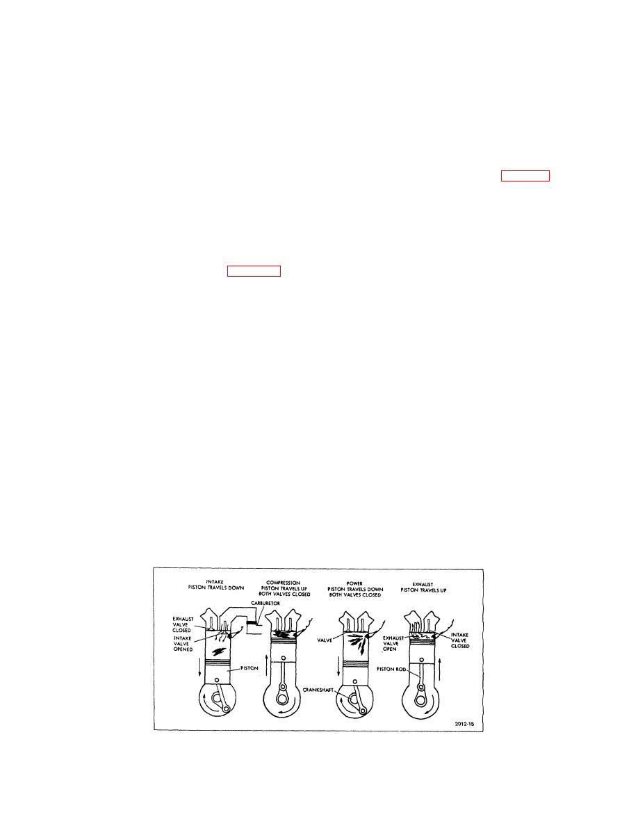
FOUR-STROKE CYCLE (see figure 4-1).
4-1.
PRINCIPLES CF OPERATION.
4-2. In the first part of this section, the principles of
4-7. INTAKE STROKE. The piston begins its intake
operation of the major assemblies of the fork lift truck will
stroke at the top of its travel in the cylinder with the
be explained.
camshaft opening the intake valve for that cylinder. The
intake stroke is a downstroke of the piston, which with
the intake valve open produces a suction from the
4-3.
ENGINE.
cylinder through the valve and intake manifold to the
4-4. The engine used in the truck (see figure 1-2) is a
carburetor. This suction draws a charge of air and
six cylinder, four stroke cycle gasoline engine of
vaporized gasoline into the cylinder. At the end of the
conventional L-head design, with battery and coil
intake stroke, the intake valve closes, Since the exhaust
ignition. One updraft carburetor supplies fuel-air mixture
valve is also closed at this time, the full charge (in
to all cylinders through a manifold. Exhaust from all
compressible gaseous form) is trapped in the cylinder
cylinders is delivered to a common exhaust system by
ready to be compressed.
an exhaust manifold. A camshaft in the engine block,
driven by the crankshaft through gears, turns at half
4-8. COMPRESSION STROKE. As the crankshaft
crankshaft speed to operate (and time) the valves and
continues to turn the piston returns upward to compress
ignition distributor, and drive the oil pump and fuel pump,
the fuel charge in the cylinder to about one-seventh its
The camshaft drive gear is positioned in relation to the
volume at the end of the intake stroke.
crankshaft so valves and ignition will operate at the
correct time in relation to piston travel which is controlled
NOTE
by the crankshaft. Hence, the expression "timing" of the
The
higher
the
degree
of
valves or ignition. Note that two revolutions of the
compression (compression ratio) the
crankshaft cause only one revolution of the camshaft,
more energy will be obtained from a
which results in two upstrokes and two downstrokes of
given quantity of fuel.
The
each piston to complete a cycle.
compression ratio of the engine is
limited by the grade of fuel for which
4-5. In the following explanation, a cycle of one
the engine is designed, and is as
cylinder will be discussed. What is said of one cylinder
high as practical for this application.
is true of each of the others; however, consider that each
piston (in firing order) lags behind the one ahead of it by
120 degrees of crankshaft rotation.
Figure 4-1. Four Stroke Engine Cycle
4-1
|
|
Privacy Statement - Press Release - Copyright Information. - Contact Us |