 |
|||
|
|
|||
|
|
|||
| ||||||||||
|
|
 c. Installation. Reverse a. above.
d. Adjustment. Refer to paragraph 6-25h.
6-27. PROPELLER SHAFT.
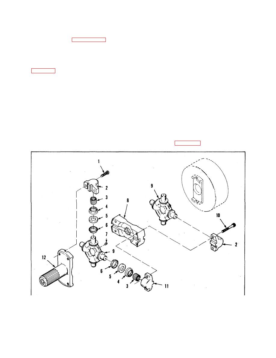
a. Removal and disassembly.
OE or specified lubricant immediately on drying. Avoid
handling dry parts with bare hands before applying
(1) Remove lock wire and take out screws (1
lubricant.
and 10, figure 6-14).
c. Inspection. Inspect bearings, rollers, and bearing
(2) Tap or pry stub yoke (12), as needed, to free
surfaces of spiders for galling, rust, or signs of wear or
bearings (2 and 11) from arced pilot surfaces of yoke,
failure. Inspect all splines for signs of damage or wear.
and coupling plates (8). Remove bearing (2) with rollers
Check all threads for stripping or cross-thread damage.
(3), collar (4), cork washer (5), and dust shield (6).
Check all flanges and machined surfaces for nicks or
Remove rear spider (9).
dents.
(3) Pry coupling plate from front spider (9) and
d. Assembly and installation.
pry spider from handbrake' drum to free remaining
bearings. Remove bearings. Discard cork washers (5).
(1) Install stub yoke splined end as far as it will
go into transmission output shaft.
b. Cleaning. Clean all parts thoroughly in SD.
Probe lubrication passages through fitting (7) and
(2) Install items 2, 3, 4, 5, 6 and 11 as illustrated
spiders, to be sure no foreign matter or hard grease
horizontally in Figure 6-14, to both spiders (9). Squeeze
soap will prevent lubrication. Coat reusable parts with
1.
Capscrew
5.
Washer
9. Universal joint spider
2.
Needle bearing
6.
Dust shield
10. Capscrew
3.
Rollers
7.
Lubrication fitting
11. Needle bearing
4.
Collar
8.
Coupling plate
Stub yoke
Figure 6-14. Propeller Shaft, Exploded View
71
|
|
Privacy Statement - Press Release - Copyright Information. - Contact Us |