 |
|||
|
|
|||
|
|
|||
| ||||||||||
|
|
 5-73. STEERING SYSTEM.
5-74. STEERING LINKAGE ADJUSTMENT (FIGURE
5-12).
a. Assemble ball joint (1) on the cylinder so that the
thread engagement is approximately 1-1/2 inches.
b. When performing adjustments in c. and d.
below, there should be no restraint on the cylinder or
pitman arm due to stops on trailing axle. To insure this,
ball joint (2) should be removed from the steering axle
bellcrank, but should be maintained in line with the hole
in the bellcrank.
c. With drag link (3) in place, turn steering wheel
full right with stop screw (4) backed off. Remove ball
joint (5) from pitman arm and pull drag link until the
cylinder (6) is at the end of stroke. Adjust ball joint and
temporarily assemble in pitman arm. Turn stop screw
until it touches pitman arm. Disconnect ball joint from
pitman arm and then three turns counterclockwise to
increase drag link length. Assemble to pitman arm.
Back off pitman arm with steering wheel, turn stop screw
one additional turn and lock in position with locknut.
d. Turn steering wheel full left with stop screw (7)
backed off until steering cylinder has extended 11-1/2
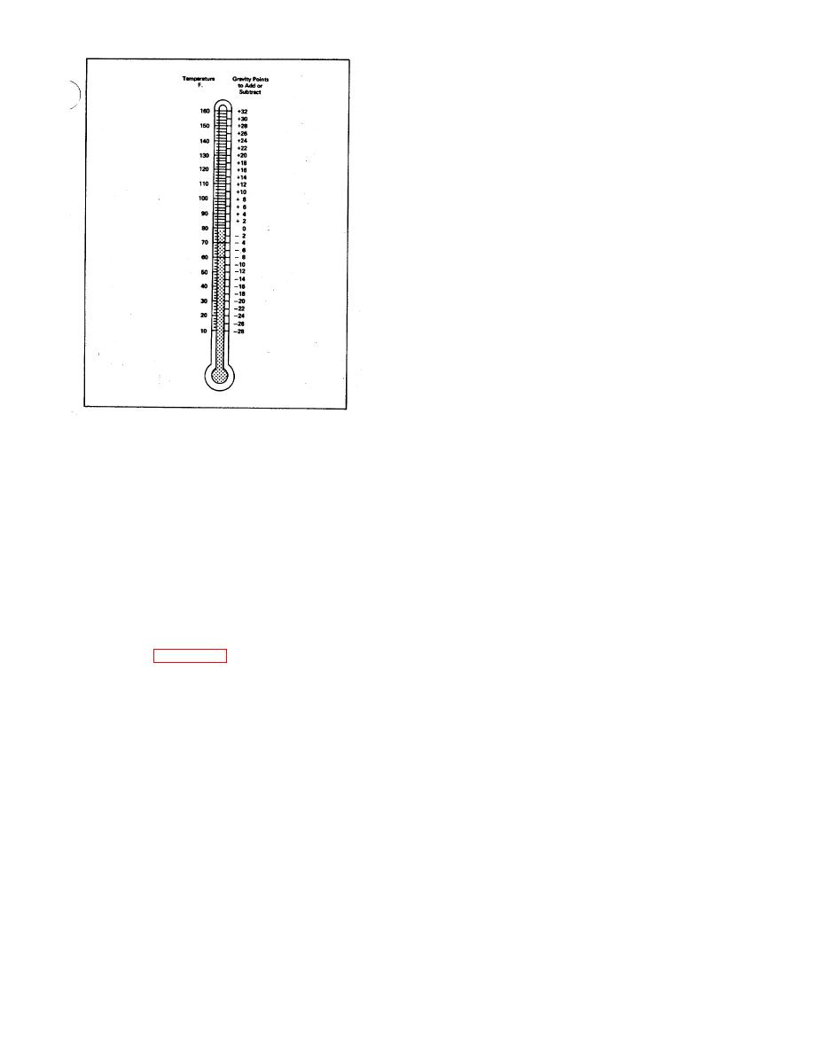
Figure 5-11. Battery Test
inches from adjusted position for right turn, as in c.
above. Bring stop screw in contact with pitman arm and
indicates a fully charged battery. A specific gravity
lock in place with lock nut.
reading of 1.220 or less in each cell indicates that the
e. Adjust rod (8) so that equal angles of steering
battery must be recharged or replaced.
wheels are obtained when steering wheel is turned from
full right to full left. Major adjustment of rod (8) length
NOTE
must be made using only ball joint (2) while rod is
A temperature-corrected specific
threader into cylinder to make dimension 12-3/4 inches.
gravity measurement is obtained by
Final adjustment may be made by turning rod (8) with
adding 0.004 to the actual hydrometer
ball joint (2) assembled in bellcrank. Do not turn rod
reading for each 10 deg F the
more than one turn in either direction or the thread
electrolyte is above 80 deg F or
engagement will be below minimum required.
subtracting 0.004 from the actual
f. Before final clamping of rod (8), position cylinder
hydrometer reading for each 10 deg F
as shown.
the electrolyte is below 80 deg F, as
shown in figure 5-11.
NOTE
After final adjustment, the entire
5-71. ADDING WATER TO BATTERY. The water in
linkage and wheels must be stopped
the battery electrolyte solution evaporates at high
only on the pitman arm stop screws
temperatures or with excessive charging rates. Inspect
(4 and 7).
Cylinder should have
the electrolyte level and add distilled water when
approximately 1/4 inch of stroke left
necessary to bring electrolyte level to 3/4 inch above the
at full right or full left turn.
plate separators.
5-75. SERVICE BRAKE SYSTEM SERVICING.
5-72. BATTERY CLEANING. The top of the battery
must be kept clean. Tighten vent plugs and clean
5-76. WHEEL BRAKE ADJUSTMENT. Since the wheel
battery with a brush dipped in an alkaline solution such
brakes used on the trucks are self-adjusting, no manual
as ammonia or a solution of bicarbonate of soda and
adjustment is required for the life of the brake linings.
water. If terminals and cable clamps are corroded,
However, two hexagon loads extend through each
disconnect cables and clean in same manner as battery.
backing from the adjusting cams. If the drums are worn
from long service, to the extent that they cannot be
readily removed
37
|
|
Privacy Statement - Press Release - Copyright Information. - Contact Us |