 |
|||
|
|
|||
|
Page Title:
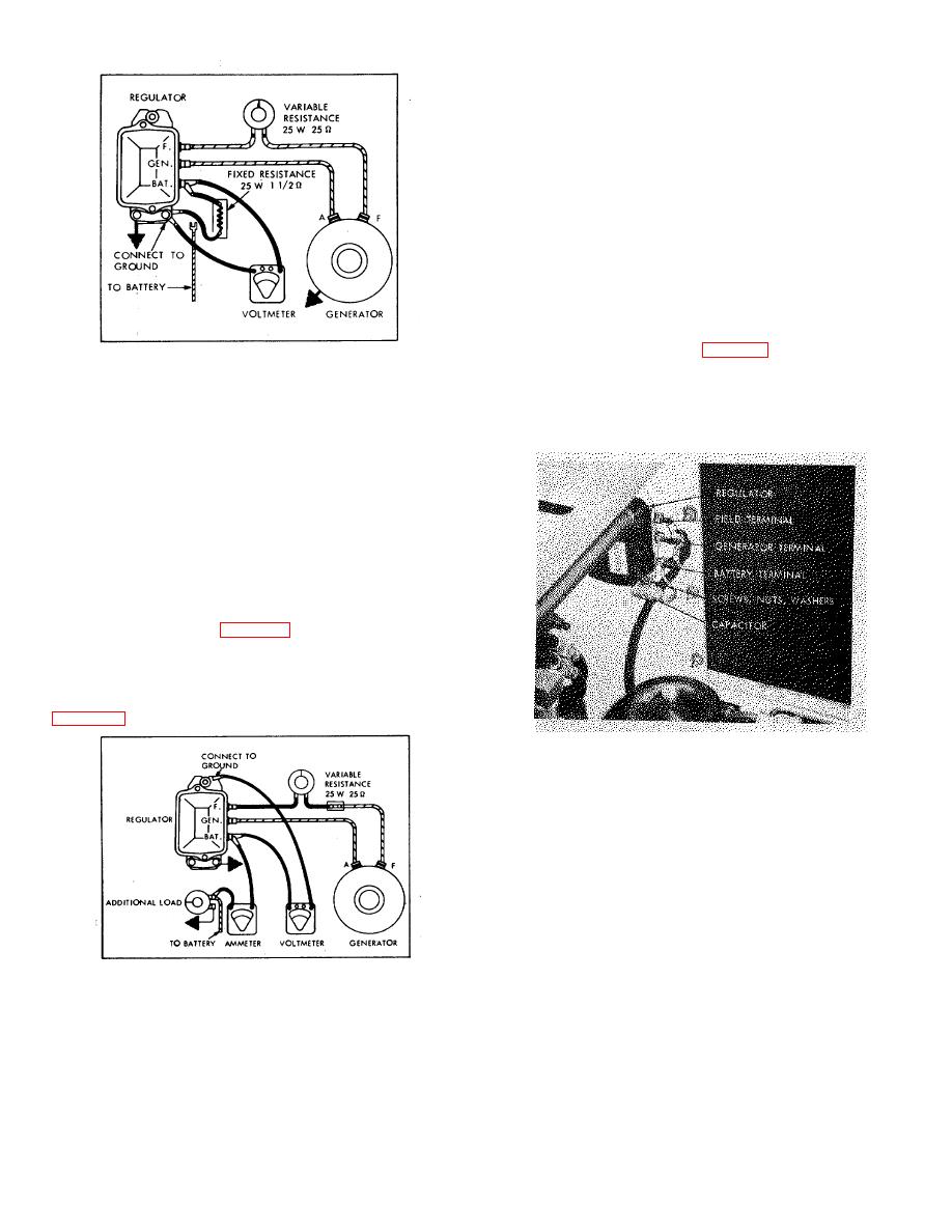
Figure 5-8. Voltage Regulator Test Setup |
|
||
| ||||||||||
|
|
 (2) Turn on all accessory load (lights) and connect
an additional load across the battery (such as a carbon
pile or bank of lights) so as to drop the system voltage
approximately one volt below the voltage regulator
setting.
(3) Operate generator at specified speed for 15
minutes with cover in place. (This stabilizes operating
temperature.)
(4) Cycle generator with variable resistor and note
current setting.
5-68. GENERATOR REGULATOR REPLACEMENT.
a. Removal.
(1) Disconnect and tag leads at BAT, GEN
and F terminals of regulator (fig. 5-10).
Figure 5-8. Voltage Regulator Test Setup
CAUTION
(2) Move voltmeter lead from GEN to BAT terminal.
Lead at BAT terminal is a hot lead.
Operate generator at charging speed for 15 minutes.
Do not let it contact the vehicle
frame.
NOTE
Disregard amount of current flowing
during this test: however, it is
important that the ignition be the only
electrical load on the system at this
time.
(3) Cycle the generator with the variable resistor, to
a 4 volt reading at the GEN terminal, then cut out the
resistor and note voltage reading at the BAT terminal.
Compare with values in Table 2-1.
c. Current Regulator Test.
(1) Connect ammeter into charging circuit, as in
Figure 5-10. Regulator, Installed
(2) Remove three holddown screws, nuts and
washers, and remove regulator and radio suppression
capacitor.
b. Installation. Reverse procedure in a. above,
connecting capacitor lead to the regulator BAT terminal.
5-69. BATTERY SERVICING.
5-70. SPECIFIC GRAVITY TEST. Specific gravity
testing of the battery electrolyte determines the state of
charge in each battery cell. Use a hydrometer and
Figure 5-9. Current Regulator Test Setup
thermometer, correcting the hydrometer reading for
temperature. A corrected specific gravity reading of
1.275 in each cell
36
|
|
Privacy Statement - Press Release - Copyright Information. - Contact Us |