 |
|||
|
|
|||
|
Page Title:
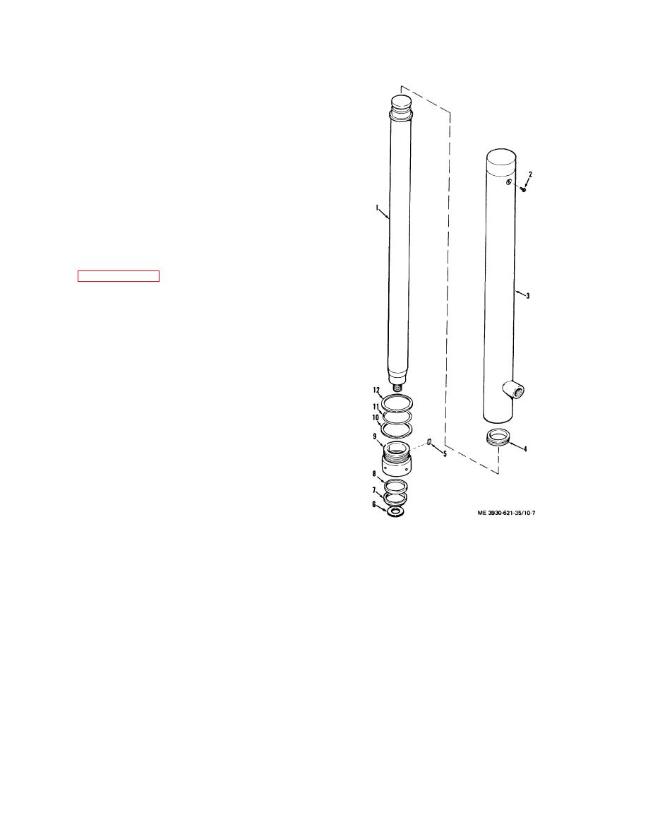
Figure 10-7. Single cylinder assembly, exploded view. |
|
||
| ||||||||||
|
|
 TM 10-3930-621-34
f. Using a hoist, remove cylinder assembly from
intermediate mast (7) and place on supports to prevent
rolling during disassembly.
10-24. Disassembly
a. Refer to figure 10-7 and disassemble as follows:
b. Remove gland nut (9) from tube (3) with spanner
wrench and discard locking pellets (5).
c. Remove spacer (6), wiper ring (7), and packing
(8) from gland nut (9). Discard wiper ring and packing.
d. Remove backup ring (10), packing (11), and
stop ring (12) from ram (1). Discard backup ring and
packing.
e. Carefully slide ram (1) from tube (3) and remove
wear block (4) from ram.
f. Remove bleed screw (2).
10-25. Cleaning, Inspection, and Replacement
Refer to paragraph 10-19.
KEY to fig. 10-7
1. Ram
7. Wiper ring
2. Bleed screw
8. Packing
3. Tube assembly
9. Gland nut
4. Wear block
10. Backup ring
5. Pellet
11. Packing
6. Spacer
12. Stop ring
Figure 10-7. Single cylinder assembly, exploded view.
10-15
|
|
Privacy Statement - Press Release - Copyright Information. - Contact Us |
