 |
|||
|
|
|||
|
Page Title:
Figure 9-2. Checking control spool rotation. |
|
||
| ||||||||||
|
|
 TM 10-3930-621-34
c. Column.
(1) Remove screws (14), brush assembly (15), and
connector (13) from column (36).
(2) Working through brush plate opening,
disconnect horn wire (33) from contact ring (34).
(3) Remove horn wire (33), ferrule (25), spring (26)
and washer (27) by slowly pulling wire from shaft (32).
(4) Remove retaining ring (28) from column (36) and
slide shaft and bearing from column (36).
(5) Remove bearing retaining ring (29), press off
bearing (30), and remove other bearing retaining ring
(31) from shaft (32).
(6) Mark two bolt hole locations on column, so ports
will be in proper direction when assembled.
(7) Remove column bolts (37) and column (36) from
mounting plate (17).
d. End Plate.
(1) Clamp assembly in vise with end cap (20) up and
remove screws (19).
(2) Remove end cap (20), rotor (21), plate (22), and
drive (23) from control assembly housing (48).
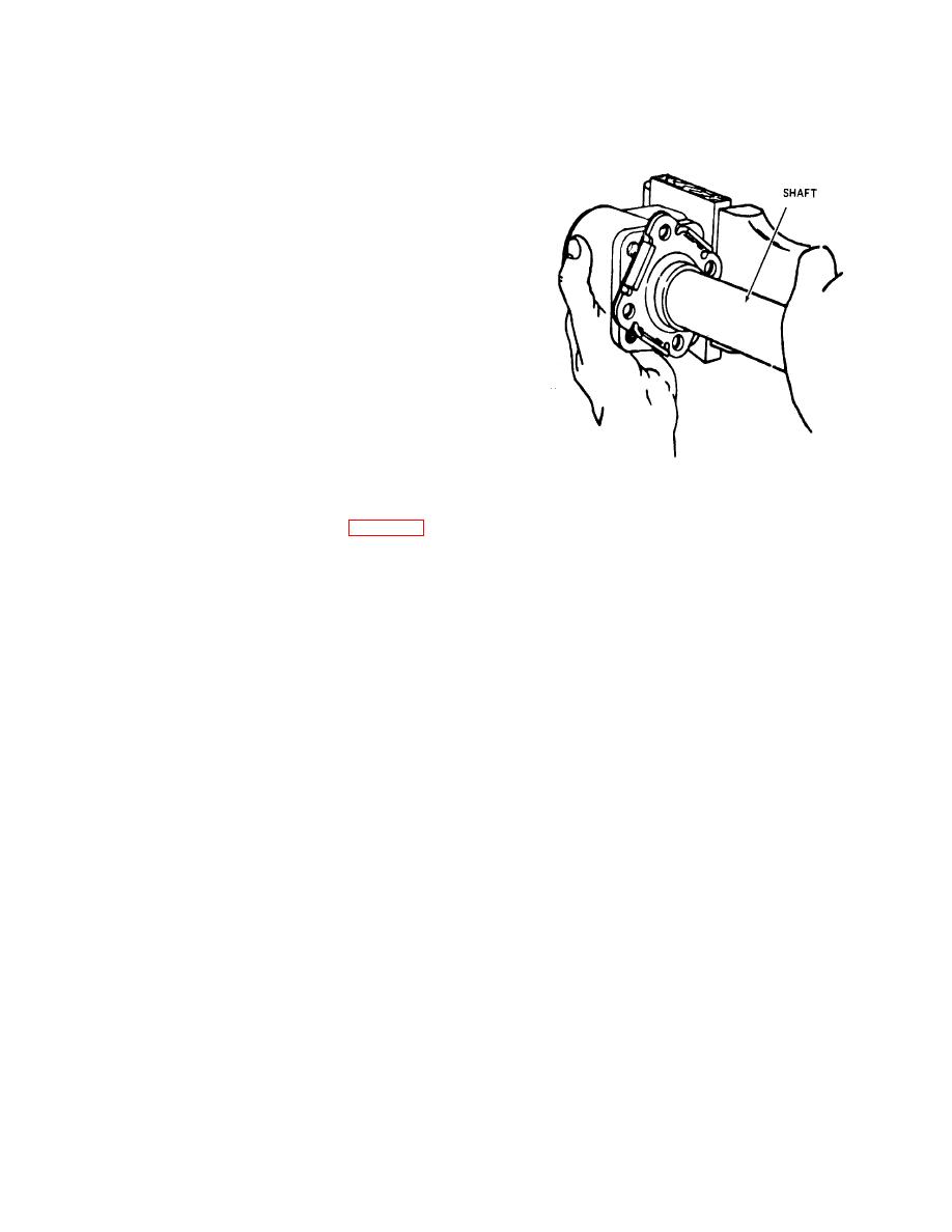
Figure 9-2. Checking control spool rotation.
e. Control Spool Rotation. Remove control assembly
(38) from vise and check for free rotation of control spool
(50) and sleeve (49), using shaft (32). See figure 9-2.
9-3
|
|
Privacy Statement - Press Release - Copyright Information. - Contact Us |
